Classifications provide additional control over the content of schedule tables. You can include:
- only those objects that meet the classification criteria.
- classification definitions as columns.
- additional information from property sets you create and attach to individual classifications
So you want to place new VAV boxes in a schedule without scheduling the existing VAV boxes that you have in your project. You can do that by creating some CLASSIFICATIONS. Classifications can be used for many different things such as scheduling only a particular pipe size, or scheduling interior lights separate from exterior lights. The possibilities are limitless.
In our example, we need to start by creating our PHASE classification.
- Click Format menu and go to the Style Manager.
- Expand Multi-Purpose Objects, and expand Classification Definitions.
- Select the classification definition.
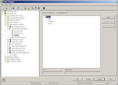
- On the Classifications tab, click Add.
- Select the new classification, and enter "Phase" under Item.
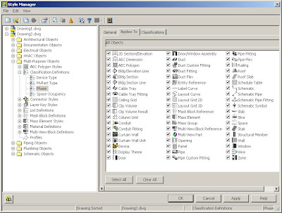
- Click the "Applies To" tab, and Select All. This way, we can assign any object to be part of any of the phases we create. In other circumstances, you could select only Pipe, or only Devices if you only want those objects to be part of this classification.
The next thing we need to do is go to the Classification Tab and click on the Add button and create a New, Existing and Demo classifications like the picture below.
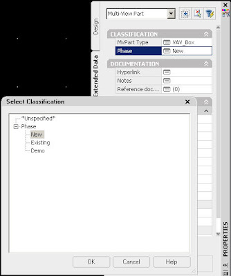
Now that we have the classifications set up, we can now apply them to our objects and to our schedules. You can change the classification of a specific object on the Extended Data tab of the Properties palette. If this change causes an object to not display, a warning dialog appears on your drawing screen.
Now that we have assigned our objects to our phase classifications, we can schedule our objects. The classification criteria that an object must satisfy needs to be included in the schedule created from a schedule table style. You can specify more than one classification for an object type. You can specify those criteria in the schedule table style. In our case, only VAV boxes that are in the New classification will be included in the schedule table.
- Click Format menu and Style Manager.
- Expand Documentation Objects, and expand Schedule Table Styles.
- Select the schedule table style that you want to change.
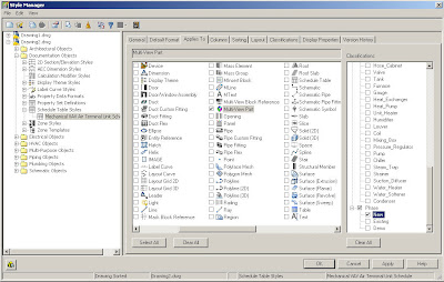
- Click the Applies To tab, and select the object types to be tracked for schedule tables using this style. In this case, it will be MvParts.
- To specify classification criteria, expand a classification definition, and select one or more classifications. In our example, we can select a phase classification of New. For an object to be included in schedules of this style, its object style must specify New for the phase classification, and the classification.
Classifications enable us to sort objects by creating a classification style that contains user-defined values to choose from. These classification styles are stored within the object style. You can use the classification styles to display and schedule objects. Autodesk Building Systems automatically classifies objects such as MvPart, Devices and fittings. This means when you insert an air terminal into your drawing, the air terminal is classified as an MvPart with an Air_Terminal type. This enables you to create a schedule that only contains air terminals, without having to include all of the MvParts in your drawing. You can take this another step further by creating a sub-type under Air_Terminal such as diffusers and grills if you wanted to schedule them in separate schedules.
Because most equipment in ABS are either Devices or MvParts, most of our schedule styles will use classifications to ensure that the schedule table is only populated with data from the desired part types.