Monday, December 15, 2008

Autodesk to Acquire BIMWorld

http://money.cnn.com/news/newsfeeds/articles/prnewswire/200812150800PR_NEWS_USPR_____SF52141.htm

SAN RAFAEL, Calif., Dec. 15 /PRNewswire-FirstCall/ -- Further enhancing its portfolio of solutions for building information modeling (BIM), Autodesk, Inc. (Nasdaq: ADSK), a leader of design innovation software and technologies, announced that it has signed a definitive agreement to acquire substantially all of the assets of BIMWorld, a privately-owned business specializing in the production and distribution of branded BIM content for building product manufacturers. Terms of the acquisition were not disclosed.

Autodesk plans to combine BIMWorld with Autodesk Seek, its online source for building product design information that allows architects and engineers to search, select and specify building products directly from their design applications. Autodesk Seek is a search-based Web service available in the 2009 U.S. versions of Autodesk’s Revit-based software applications for BIM, as well as AutoCAD, AutoCAD Architecture and AutoCAD MEP software. Autodesk Seek is also available through standard browsers at http://seek.autodesk.com.

"The vision for Autodesk Seek is to be a leading online destination and one-stop-shop for high quality building product information and design files," said Jeff Wright, Autodesk senior director of Content Solutions. "By joining forces with the BIMWorld team, we will strengthen the leadership of Autodesk Seek as a powerful marketing solution for building product manufacturers, and by further leveraging our strategic content partners, accelerate designers’ access to a breadth of rich product information and design files for use during the design process."

Friday, December 12, 2008

Assigning IFC Classifications To AutoCAD MEP Objects

The International Alliance for Interoperability (IAI) has established international standards for common architectural and construction objects in the building industry. In particular, the International Alliance for Interoperability developed an Industry Foundation Classes (IFC) data model to define CAD graphic data as 3D real-world objects. The IFC file format provides interoperability between IFC-certified software applications and reduces loss of information when files are transmitted.

You can export drawings saved in AutoCAD MEP to the IFC format and then import the file into another IFC-certified application like Revit. The dimensions of any 3D architectural objects, including MEP objects, are preserved when exporting to IFC.

Before you can export an MEP drawing file to IFC, you need to map each MEP object to the appropriate IFC classification. This step allows MEP objects developed in AutoCAD MEP to display properly in other IFC-certified applications.

You can assign IFC classifications to the following MEP objects:

  • Cable tray
    Cable tray fitting
    Conduit
    Conduit fitting
    Duct
    Duct custom fitting
    Duct fitting
    Duct flex
    Hanger
    Multi-View part
    Panel
    Pipe
    Pipe custom fitting
    Pipe fitting
    Pipe flex

The IfcShareBldgElements (MEP).dwg drawing file contains the IFC classifications for these MEP objects. This file resides at \Documents and Settings\All Users\Application Data\Autodesk\ACD-MEP 2009\enu\Styles. The following IFC object classifications are supported in AutoCAD MEP:

  • IfcDistributionChamberElement
    IfcDistributionControlElement
    IfcDistributionFlowElement
    IfcEnergyConversionDevice
    IfcFlowController
    IfcFlowFitting
    IfcFlowMovingDevice
    IfcFlowSegment
    IfcFlowStorageDevice
    IfcFlowTerminal
    IfcFlowTreatmentDevice
    IfcElectricDistributionPoint

Use the following procedure to assign IFC classifications to MEP objects prior to exporting to an IFC file:

To set up IFC classifications in AutoCAD MEP

  1. Click File menuOpen to navigate to \Documents and Settings\All Users\Application Data\Autodesk\ACD-A 2009\enu\Styles directory and open the IfcShareBldgElements (MEP).dwg file.
  2. Click Format menu Style Manager.At the Command prompt, enter AecStyleManager.
  3. Expand Multi-Purpose ObjectsClassification DefinitionsifcObjectClassification in the left pane.

  4. Right-click ifcObjectClassification and click Copy.
  5. Click Cancel to close the Style Manager.
  6. Click File Close to close the IfcShareBldgElements (MEP).dwg drawing file without saving it.

To map MEP objects to IFC

  1. Open a drawing file that contains the MEP objects where you will assign IFC classifications.
  2. Click Format menu Style Manager. At the Command prompt, enter AecStyleManager.
  3. Expand Multi-Purpose ObjectsClassification Definitions.

  4. Right-click Classification Definitions and click Paste.
  5. Click ifcObjectClassification in the left pane and then the Applies To tab in the right pane to see the applicable MEP objects (as shown below).

  6. Click OK.
  7. Right-click an MEP object in your drawing and click Properties on the context menu.
  8. Click the Extended Data tab on the Properties palette.
  9. Under Classification, click next to IfcObjectClassification to open the Select Classification dialog.


  10. To apply a new IFC classification to the selected MEP object, choose an IfcSharedBuildingServicesElement property from the list and click OK.
    Your selection appears next to IFCObjectClassification on the Extended Data tab on the Properties palette. Repeat this step for each MEP object in your drawing.
    You can also click on the Quick Select icon at the upper right corner of the Properties palette to select multiple MEP objects with the same classification and then classify them on the Extended Data tab. You might be unable to map some MEP objects directly to IFC. For example, you might choose to map an MvPart to IfcFlowFitting if the classification is Junction_Box, to IfcFlowMovingDevice if the classification is Fan, or to IfcFlowTerminal if the classification is Air_Terminal. Alternately, you can also leave the IFC classification as unspecified.
  11. Save your drawing file before exporting it to an IFC file.

To export or import IFC files

  1. To export a drawing to IFC, click File menu IFC Export to IFC.To export a drawing to IFC, at the Command prompt, enter AecIfcExport.
    Following the export, you can open the new IFC file in Revit. The IFC classifications appear for each object that you defined previously.
  2. To import an IFC file back into AutoCAD MEP, click File menu IFC Import from IFC.To import an IFC file back into AutoCAD MEP, at the Command prompt, enter AecIfcImport.
    The imported IFC file is imported as a referenced drawing (xref). You can check that the MEP objects were properly preserved.
  3. To edit objects in the imported file, right-click an object and click Edit Xref in-place.

Importing a large IFC file may fail due to the limitations of memory addressing on 32 bit operating systems. In this case the only solution is to use a 64 bit operating system.
Duct, Pipe, Conduit and CableTray elbow fittings in Rise and Drop display as 1-line when using Import from IFC. To allow the fittings to display in Model view, perform the following:
Go to Display Manager>Sets>MEP Design - Plan and activate the Sketch Check Box for Mass Element. Perform the same procedure for other Sets that will be used as the UI Display Configuration.


Tuesday, November 18, 2008

Content Extension for AutoCAD MEP 2009

Release Date: 2008-10-09

The US Content Extension for AutoCAD® MEP 2009 software provides new pipe and MvParts catalogs for water and wastewater design. By downloading this extension, you will have access to components and parts specific to the water and wastewater design projects, including, large diameter pipe fittings, numerous valves, aerators, centrifuges, classifiers, conveyors, blowers, screens, gates, pumps as well as other equipment.

This new content can be downloaded for free from your Autodesk subscription login.


Parts added via this Content Extension

Below is a list of parts types added to both the US Imperial and US Metric part catalogs.

MvParts\Electrical
  • Starter
    Controllers
    Interface Stations
MvParts\Mechanical
  • Aeration Disc Diffuser
    Blowers
    Centrifuges
    Classifier
    Conveyors
    Gates
    Heat Exchangers
    Mixers
    Pumps
    Screen
    3-Way Valves
    Air Valves
    Backflow Preventers
    Ball Valves
    Butterfly Valves
    Check Valves
    Cone Valves
    Diaphragm Valves
    Gate Valves
    Globe Valves
    Knife Valve
    Mud Valves
    Valve Actuators
Pipe

  • Buttweld Cross
    Buttweld Elbows
    Buttwled Reducer
    Buttweld Tee
    Buttweld Laterals
    Flanges
    Flanged Cross
    Flanged Elbows
    Flanged Reducer
    Flanged Tee
    Flanged Laterals

General Installation Information

Before You Begin to install the content extension, keep in mind to back up all custom parts, including the .dwg, .xml and .bmp files.

Installation Location

The content will be added to the MEP Catalog Content location specified during the original install of AutoCAD MEP 2009.

The Windows XP default location is:

C:\Documents and Settings\All Users\Application Data\Autodesk\ACD-MEP 2009\enu\Aecb Catalogs.

The Windows Vista default location is:
C:\ProgramData\Autodesk\ACD-MEP 2009\enu\Aecb Catalogs.


Note: If you have moved your catalogs after installation to a new location the Content Extension parts will not be installed to the new location.

After the content extension is installed you will need to go into your options, and add the two catalogs to the MEP Catalog and then Regenerate the Catalogs.

Monday, November 17, 2008

Creating Annotative Tags

Creating Annotative Tags in AutoCAD Archtitecture

I get asked about how to create smart tags in AutoCAD MEP all the time, and I think I wrote an article on it at one time, but my memory fails me sometimes, but I ran across David Koch's blog in regards to creating smart tags that are annotative. So if you can't find this information in my search, take a look at Davids' blog.

Thanks.

Monday, October 20, 2008

AutoCAD MEP® 2009 Update 2 Now Released

autocad_mep_suite_2009_update2_win_32bit.exe

autocad_mep_suite_2009_update2_win_64bit.exe


The following defects have been fixed in AutoCAD MEP 2009 Update 2

Duct
  • Duct Sizing should more accurately produce the correct size in metric units.

Electrical

  • The Load property on Devices will now schedule the loads of each phase instead of only phase 1.
  • Object Snaps on scaled Devices will now behave more consistently.
  • Devices which contain annotation will produce an image in the Property Palette which matches the image in the Select a Style dialog
Pipe
  • Using grips to modify a Pipe layout during a Reference Edit session no longer causes disconnections in the pipe layout.
  • AutoLayout should not produce overlapping pipe segments when connection two existing pipes to each other.

Tool Palettes

  • Multi-view Part tools will respect Part Size Name when executed.

Miscellaneous

  • Invalid Enum Map String message is no longer encountered when using the MvPartModify command on a multi-view part which does not exist in the active catalog.

The following defects were fixed with AutoCAD MEP 2009 Update 1 and are also fixed in AutoCAD MEP 2009 Update 2:

Catalog editor

  • Unable to Write Check Permissions error occurs when copy and paste parts into the same catalog.

Duct

  • Duct sizing does not always provide the expected size when using Metric units

Electrical

  • Power Totals tool does not always state the correct load.

Pipe

  • Pipe segments will be offset from each other when using justification which is not Center/Center.
  • Insulation will not be applied to pipe fittings when using the match properties.
  • In some instances pipe object are not visible until a regenerate is performed.

MvPart

  • Invalid Enum Map String error when using MvPartModify on a multi-view part created via MvPartConvert command.

System

  • AutoCAD warning message when saving an External Reference.

General Updates to AutoCAD Architecture

The following defects have been fixed in AutoCAD Architecture 2009 Update 2

Annotation scaling

  • Multi-view blocks inserted from user created tools did not scale properly when used in subsequent drawings or sessions.

Drawing management

  • Projects created from project templates did not inherit the correct sheet storage location property.
  • Projects created from project templates did not inherit sheet subset storage location information.
  • The application would occasionally crash when creating project details.

GBXML

  • Surfaces belonging to different walls would export with the same CadObjectId.

IFC

  • Spaces, railings, footings, and column objects might be exported with an incorrect object type identifier in some localized releases.
  • Half spaces would be imported as large modifiers.
  • Slab fascias and soffits would not properly export in some localized releases.
  • Level and elevation info would be created in reverse order when an IFC file was imported into a project.
  • Material sets applied to walls of type "Shared" would not export correctly.

Schedules

  • The schedule quantity column evaluated property values without first applying the property data format.

Wall objects and opening endcaps

  • Certain endcap configurations might cause walls to disappear in 3d isometric views.
  • Some walls might not draw completely at a locked z elevation.
  • Using "Add selected" for anchored doors, openings, and windows could cause an application crash in some circumstances.
  • Walls might fail to clean up properly across xrefs if the host drawing used different drawing units than the xref.

Miscellaneous

  • Tooltips would appear for AutoCAD entities even when ROLLOVERTIPS was set to zero.
  • Saving a drawing to the 2004 file format would take an exccessive amount of time.
  • Export to AutoCAD might cause an application crash in some circumstances.

The following defects were fixed with AutoCAD Architecture 2009 Update 2:

AModeler

  • The application might crash when cutting or refreshing sections or elevations containing certain structural members.

Drawing Management

  • For localized versions of AutoCAD Architecture, callouts and labels would occasionally fail to resolve when dropping views.
  • The application might crash when viewing the external references of a project drawing that was resaved as a different project drawing type.
  • It was not possible to drag a project entity from one file to another when hardware acceleration was enabled, if the host drawing did not use the 2d wireframe visual style.
  • The application might crash when plotting immediately after cancelling a previous plot job.

IFC

  • Fillet radii would not be imported reliably for certain parameteric profiles.
  • Parametric profiles without voids would not be imported reliably.
  • Spaces with clipping and holes would not import reliably.
  • Wall styles would not be reliably converted and mapped on import.
  • Curtain walls might not be import properly on localized versions of AutoCAD Architecture.

GBXML

  • gbXMLspan would export a value 1000 times too large for AirChangesPerHour in metric drawings.

OMF

  • The application would occasionally crash on shutdown.

Wall Objects

  • The face of a wall might not draw correctly in isometric view for certain endcap configurations.

Display System

  • Autodesk Civil 3D users could end up with a style referencing a non-existent hatch.

Miscellaneous

  • Memory would not be released to Windows when closing a drawing.

General Updates to AutoCAD

The following defects have also been fixed:

3D Navigation Tools

  • When you use the ViewCube in some drawings, AutoCAD freezes.
    .NET API
  • If you create a wipeout object through .NET API, a fatal error may occur.

Annotation Scaling

  • The scale of annotative text changes when you use LISP entmod() to change the properties of the annotative text.

Attributes

  • When a drawing contains xrefs, the -ATTEDIT command fails.

Autodesk Buzzsaw

  • In the File Navigation dialog box, when you use the Add a Buzzsaw location shortcut option, AutoCAD crashes.

Blocks

  • When you copy and paste a dynamic block, associative hatches do not work.
  • After you redefine a block definition, associative hatches in dynamic blocks display incorrectly.
  • When you open a drawing, a polyline in a block may have a very large width.
  • After you open a drawing, some dynamic blocks lose their dynamic properties.

Data Extraction

  • Data Extraction cannot finish operations in some cases.
  • The Data Extraction Combine Record Mode > Sum values option does not work correctly.

DGN Support

  • When you import some DGN files, AutoCAD crashes.

DIM

  • If alternate units is on and you edit dimension text, the alternate units text is duplicated.

Export a Layout to Model Space

  • If .NET 3.5 Service Pack 1 is installed and you use the EXPORTLAYOUT command on some layouts, AutoCAD may stop responding.

External Reference ESW

  • The FIND command performs slowly when you search for text.

Groups

  • Rollover highlighting does not go away.

Hatch

  • When you bind a drawing with an xref that contains annotative hatches, AutoCAD crashes.

Hide/Shade

  • When you use the HIDE command with a drawing that contains text, some objects may not be hidden.

Image

  • When you attach a corrupted raster image to a drawing, AutoCAD crashes.

Layer

  • When you zoom to a locked viewport, the Layer palette updates

Layouts

  • When you attempt to switch layouts in drawings, an Out of Memory crash may occur.

Materials

  • When you import a 3DS file with texture, AutoCAD may crash.

Menu Browser

  • Some menu macros do not work.

Multileader (mleader)

  • Mleader custom arrowheads are not brought over to the drawing from the Tool palette.

Multiline Text (mtext)

  • When you edit mtext in a viewport, it may be duplicated in other viewports.

Open/Save

  • Osnaps on polylines and mesh objects do not work correctly.

Plot

  • When you plot upside-down, an OLE object does not plot correctly.
  • A drawing that contains hatches and gradients may plot slowly.
  • When plot area is set to View, AutoCAD LT may crash.

Publish

  • When you attempt to publish multiple sheets with PUBLISHCOLLATE=1, only the first sheet of the set is plotted.

Quick Properties

  • When you edit multiple mtext objects through the Quick Properties palette, AutoCAD crashes.

RECOVER

  • When you render some drawings, AutoCAD runs out of memory.

Ribbon

  • If the ribbon is displayed and you select portions of a mtext object that contains multiple formats, the mtext object becomes distorted.

Selection

  • When you select objects in groups, AutoCAD may crash.

Tables

  • When you edit text with space before or after the text within a table cell, AutoCAD crashes.

Text

  • When you move text to a new position within a drawing, it disappears.

Tool Palette

  • When you attempt to edit the properties of multiple Tool Palette tools, an Out of Memory crash may occur.

Known Issues with This Update

  • After installing this update you may receive a "Error Code: 3010" message incorrectly claiming that the update failed. You can verify this by viewing installed updates through the Windows control panel.
  • After you apply this update, you may experience the following ribbon customization-related problems:

An Incorrect or Missing Ribbon Tab

  • Known Issue: When you display a ribbon tab from a partial or Enterprise CUI file, on the ribbon, the ribbon tab displays incorrectly or is missing.
  • Workaround: To correctly display a ribbon tab, recreate the workspace used to display the ribbon tab from scratch. Do not duplicate or attempt to update the workspace. Once you create a new workspace, set the workspace current. The ribbon tab should display correctly.
  • For a partial CUI file, before you add a ribbon tab to a workspace, use the Customize User Interface (CUI) Editor to change the customization group name of the file. The customization group name is represented by the uppermost node of the tree in the Customization In pane.

A Blank Image for a Command

  • Known Issue: On a ribbon panel, the image associated with a command defined in the Command List pane displays as a blank icon.
  • Workaround: To recreate a ribbon command item on a ribbon panel, delete it. Then, from the Command List pane, add the command to the ribbon panel.

Wednesday, September 24, 2008

HVAC Load Calculation Extension For AutoCAD MEP and Revit MEP


The HVAC Load Calculation Extension by Autodesk, Inc. is a commercial and industrial HVAC (Heating, Ventilation, and Air Conditioning) load calculation software package whose calculations are based upon the ASHRAE 2005 Fundamentals radiant time series (RTS) method. The purpose of this software is to provide you with total cooling and heating loads for a building so that you may properly specify the correct size HVAC equipment (whether it is a packaged rooftop unit or a boiler). This program is geared specifically toward the HVAC engineer, architect, design/build mechanical contractor, and building maintenance supervisor.

The HVAC Load Calculation Extension is available to customers of AutoCAD MEP 2009 and AutoCAD Revit MEP Suite 2009 on Autodesk Subscription and is subject to Autodesk Subscription terms and conditions.

The Extension supports sustainable design by allowing engineers to properly size HVAC equipment without oversizing. Conventional wisdom dictates that it is better to have too much cooling than not enough. Without the ability or tools to accurately calculate heating and cooling loads, oversizing equipment is a common practice. However, oversized equipment wastes a tremendous amount of energy throughout its lifetime. In a BIM-supported workflow, analysis capabilities and calculation tools (such as this Extension) enables designers and engineers to more thoroughly investigate design alternatives and optimize their emerging design for energy efficiency and sustainability.

The HVAC Load Calculation Extension uses formulas from the ASHRAE (American Society of Heating, Refrigerating, and Air-Conditioning Engineers) Handbook of Fundamentals. This publication compiles the fundamentals of the HVAC, such as methods for calculating peak cooling and heating loads for buildings.

The Extension produces a number of reports including: a summary load breakdown by individual room; a detailed load breakdown by individual load components such as roofs, walls, people, and lighting; and a psychrometric report that includes the properties of the entering and exiting air. Some of these reports include graphs for better visualization of the load breakdowns. Users also have the ability to export custom reports to Microsoft Word or Excel applications.

The Extension is able to import building information from AutoCAD MEP or Revit MEP using the gbXML file format. This means that all pertinent information about the building can be transferred to the Extension so that very little manual data entry is needed. Once the cooling and heating load calculations are performed, the results can be exported back to AutoCAD MEP or Revit MEP for proper duct and pipe sizing.
The HVAC Load Calculation Extension includes the following basic features:
  1. Inputs for HVAC system characteristics such as supply cooling and heating temperatures, ventilation rates, fan characteristics, cooling and heating setpoints, duct sizing, and safety factors
  2. Inputs for HVAC area (room) characteristics such as wall, window, roof, door, skylight, and partition areas. In addition, there are inputs for # of people, electrical appliances, infiltration, lighting, miscellaneous, exhaust, and plenum loads
  3. Weather data from over 800 cities throughout the world
  4. A complete u-value database for common wall, roof, window, floor, and door types
  5. A complete appliance list for determining internal electrical equipment load contributions
  6. Many reports including summary, detailed, psychrometric, wall/window breakdown, 24-hour load breakdown, and graphical reports
  7. A feature that allows the user to export all inputs and outputs to custom Microsoft Word and Excel documents
  8. Equipment selection
  9. Support for both English (IP) and Metric (SI) units

Wednesday, September 17, 2008

WAN Acceleration 2009 Hotfix

Autodesk finally released a hotfix to improve the performance of saving to 2007 DWG format when running in a WAN Acceleration environment. The problem was an Autodesk problem, and not anything related to any particular Wan Accelerator as some people have thought. This is a Hotfix posted by Autodesk that you can also view from the following links...

2009 Wan Acceleration Hotfix link
2008 Wan Acceleration Hotfix link
2007 Wan Acceleration Hotfix link


Description of Problem
WAN acceleration technology typically relies on data-deduplication as a significant part of accelerating data transfer. The 2007 DWG format is written to disk with a type of error-checking that has the side-effect of nearly every byte of the file changing during full-save, even if little was changed. WAN accelerators fail to deduplicate the 2007 DWG data and must transfer nearly all bytes in the 2007 DWG file. This results in a slow-down during full-save when working over a slow WAN.

This hotfix will make a small change in the way the 2007 format DWG files are written to disk such that WAN acceleration hardware will be better able to deduplicate the 2007 DWG data; this will provide some performance gains for SAVE operations when users are saving across a WAN acceleration environment. The resulting 2007 DWG file will be readable whether or not others have this hotfix, but to achieve the best performance everyone working on the same DWG should install this hotfix.

After intalling the hotfix, you must set the Windows environment variable, ACADCOMPRESSIONMODE to 1 for it to have effect.

Note: For AutoCAD, you can often get performance gains in QSAVE operations by setting the ISAVEPERCENT system variable to 100. Using a value of 100 will maximize the chance that a QSAVE operation will use incremental-save rather than full-save. (WAN accelerator technology is able to show good performance in deduplication of 2007 DWG format files when incremental save takes place.)

Applicable Products
AutoCAD 2009
AutoCAD LT 2009
AutoCAD Architecture 2009
AutoCAD Civil 3D 2009
AutoCAD Electrical 2009
AutoCAD Land Desktop 2009
AutoCAD Map3D 2009
AutoCAD Mechanical 2009
AutoCAD MEP 2009
AutoCAD P&ID 2009
AutoCAD Raster Design 2009
AutoCAD Revit Architecture Suite 2009 (1)
AutoCAD Revit MEP Suite 2009 (2)
AutoCAD Revit Structure Suite 2009 (1)
Autodesk Inventor™ Professional 2009 (3)
Autodesk Inventor Suite 2009 (3)

(1) Apply this hotfix only if the installation includes AutoCAD 2009.
(2) Apply this hotfix only if the installation includes AutoCAD MEP 2009.
(3) Apply this hotfix only if the installation includes AutoCAD Mechanical 2009 or AutoCAD Mechanical Desktop® 2009.

Installation Instructions

To Install the WAN Acceleration Hotfix
You must have administrative privileges on your Microsoft® Windows® operating system to complete the installation process.

This installation requires you to replace the following files:
  • acdb17.dll
  • AcSignCore16.dll
After you replace these files, you must restart your system in order for this hotfix to take effect.

NOTE: Only apply this hotfix after you have installed an AutoCAD 2009-based product. This installation requires you to modify an installed product, which may cause Windows security warnings to display. For all Windows security warnings that display during installation, click Continue.

To Replace the acdb17.dll File
  1. Close all software applications.
  2. Navigate to your product installation folder; for example C:\Program Files\AutoCAD 2009.
  3. In the product installation folder, right-click the acdb17.dll file and select Properties.
  4. Click the Version tab and confirm the file version.
  5. If the file version is 17.2.56.0, 17.2.111.0, or 17.2.112.0, proceed with this installation.
  6. If the file version is greater than 17.2.112.1, do not install this hotfix.
  7. Rename the affected original file.
  8. In the product installation folder, right-click the acdb17.dll file and rename it acdb17.bak.
  9. Based on the product you have installed and its version of the acdb17.dll file, double click the appropriate file.
  10. For AutoCAD 2009-based products with the acdb17.dll file version 17.2.56.0
  11. Based on the version of your product, double-click WAN_Accelerator_Hotfix_2009_32bit.zip or WAN_Accelerator_Hotfix_2009_64bit.zip.
  12. For AutoCAD 2009 Update 1 with the acdb17.dll file version 17.2.111.0 or 17.2.112.0
  13. Based on the version of your product, double-click WAN_Accelerator_Hotfix_2009_Update_1_32bit.zip or WAN_Accelerator_Hotfix_2009_Update_1_64bit.zip.
  14. Extract acdb17.dll file to the product installation folder; for example C:\Program Files\AutoCAD 2009. NOTE: Keep the zip file that you used in step 6 open. Without opening other software applications, immediately proceed to the procedure below .

To Replace the AcSignCore16.dll File

  1. Navigate to your Autodesk Shared folder; for example: C:\Program Files\Common Files\Autodesk Shared.
  2. In Autodesk Shared folder, right-click the AcSignCore16.dll file and select Properties.
  3. Click the Version tab and confirm the file version.
  4. If the file version is 17.2.56.0 proceed with this installation.
  5. If the file version is greater than 17.2.112.1, do not install this hotfix.
  6. Rename the affected original file
  7. In the Autodesk Shared folder, right click the AcSignCore16.dll file and rename it AcSignCore16.bak.
  8. Double-click the zip file you used when you replaced the acdb17.dll file. See To Replace the acdb17.dll File, Step 6.
  9. Extract the AcSignCore16.dll file to the Autodesk Shared folder; for example: C:\Program Files\Common Files\Autodesk Shared.
  10. Restart your system.

To set the ACADCOMPRESSIONMODE environment variable

On Windows XP

  1. Right-click My Computer, and then click Properties.
  2. Click the Advanced tab.
  3. Click Environment variables.
  4. Click New to add a new system variable name and value.
  5. Set the Variable name to ACADCOMPRESSIONMODE
  6. Set the Variable value to 1
  7. Click OK until you return to the desktop

On Windows Vista

  1. Right-click My Computer, and then click Properties.
  2. Right-click My Computer, and then click Properties.
  3. Click the Advanced system settings link.
  4. Click Environment variables.
  5. Click New to add a new system variable name and value.
  6. Set the Variable name to ACADCOMPRESSIONMODE
  7. Set the Variable value to 1
  8. Click OK until you return to the desktop

To Uninstall the WAN Acceleration Hotfix

  1. In the product installation folder
  2. Delete the acdb17. dll file that you downloaded.
  3. Restore the file you renamed to the original name. See To Replace the acdb17.dll File, Step 5.
  4. In the Autodesk Shared folder
  5. Rename the AcSignCore16.dll file to AcSignCore16.dll.hotfix.
  6. Restore the file you renamed to the original name. See To Replace the AcSignCore16.dll File, Step 4.
  7. Restart your system.

For more information about this issue, I have previous posts around it
WAN war breaks out over changed file formats in AutoCAD MEP
Reduced write performance for Riverbed WAN links when working with AutoCAD MEP 2007 DWG files
WAN Accelerators Part II

Wednesday, July 30, 2008

Calculation of pipework system volumes and displaying in schedule

This tip will enable the user to automatically calculate the volume of pipework in a system, and display it in a schedule which will update itself to reflect any changes made to the system. First of all you have to make sure that you only select pipes when creating a schedule to calculate volumes, as fittings such as reducers will not allow the formula to work (having two sizes and no actual length specified).This will produce a schedule of just pipes, as expected. You will be presented with a schedule of question marks to begin with so you need to select the schedule, right click and select “add all property sets”. Now you need to add your formula column: select and right click the schedule and select “edit schedule table style”. Then pick on “add formula column”.


You will then see the “modify Formula column” dialogue box as shown:


You will need to set all of the options as shown above, and add the formula as shown. (The highlighted parts of the formula are selected from the “insert property definitions” box below.)

Once done, if you pick OK and then OK again, your schedule should have a column added to it showing volumes (in litres) for all pipes and a total volume at the bottom.


For other units of volume e.g. cubic metres you simply need to change the ratio currently set as 0.000001 in the formula. Of course this will only ever show volumes for the pipework only and not the fittings, so you may need to add a percentage to it for a more realistic figure.

http://www.autodesk.co.uk/adsk/servlet/item?siteID=452932&id=9997264&linkID=10427447

Saturday, July 26, 2008

AutoCAD MEP 2009 Service Pack 1 Released

Download the AutoCAD MEP 2009 Product Update 1 32-Bit Here

Download the AutoCAD MEP 2009 Product Update 1 64-Bit Here

Primary Issues Resolved by This Update
General Updates to AutoCAD MEP
The following issues have been fixed in AutoCAD MEP 2009 Update 1:

Catalog Editor

  • Unable to Write Check Permissions error occurs when copy and paste parts into the same catalog.

Duct

  • Duct sizing does not always provide the expected size when using Metric units

Electrical

  • Power Totals tool does not always state the correct load.

Pipe

  • Pipe segments will be offset from each other when using justification which is not Center/Center.
  • Insulation will not be applied to pipe fittings when using the match properties.
  • In some instances pipe object are not visible until a regenerate is performed.

MvPart

  • Invalid Enum Map String error when using MvPartModify on a multi-view part created via MvPartConvert command.

System

  • AutoCAD warning message when saving an External Reference.

Problems in AutoCAD MEP Reported with the Customer Error Reporting Utility
As a result of detailed information from customers who used the Customer Error Reporting Utility, a number of problems were identified and fixed. Updates have been made in the following feature areas:

  • External Reference (xref) Editing
  • Device Selection
  • Project Navigator
  • Multi-View Part Modify
  • Opening Legacy drawings

General Updates to AutoCAD Architecture
The following issues have been fixed in AutoCAD Architecture 2009 Update 1:

AModeler

  • The application might crash when cutting or refreshing sections or elevations containing certain structural members.

Drawing Management

  • For localized versions of AutoCAD Architecture, callouts and labels would occasionally fail to resolve when dropping views onto sheets.
  • The application might crash when viewing the external references of a project drawing that was resaved as a different project drawing type.
  • It was not possible to drag a project entity from one file to another when hardware acceleration was enabled, if the host drawing did not use the 2d wireframe visual style.
  • The application might crash when plotting immediately after cancelling a previous plot job.

IFC

  • Fillet radii would not be imported reliably for certain parameteric profiles.
  • Parametric profiles without voids would not be imported reliably.
  • Spaces with clipping and holes would not import reliably.
  • Wall styles would not be reliably converted and mapped on import.
  • Curtain walls might not be import properly on localized versions of AutoCAD Architecture.

GBXML

  • gbXML would export a value 1000 times too large for AirChangesPerHour in metric drawings.

OMF

  • The application would occasionally crash on shutdown.

Wall Objects

  • The face of a wall might not draw correctly in isometric view for certain endcap configurations.

Display System

  • Autodesk Civil 3D users could end up with a style referencing a non-existent hatch.

Miscellaneous

  • Memory would not be released to Windows when closing a drawing.

Problems in AutoCAD Architecture Reported with the Customer Error Reporting Utility
As a result of detailed information from customers who used the Customer Error Reporting Utility, a number of problems were identified and fixed. Updates have been made in the following feature areas:

  • 3D Visual Styles
  • Annotation Scaling
  • External References (xref) palette
  • Raster Images
  • Partial Open
  • Plot
  • Properties Palette
  • Hatch
  • Remote text (rtext)

General Updates to AutoCAD

The following issues have also been fixed:

.NET API

  • When a .NET function with a LispFunction attribute has the return type as object, an exception is thrown in AutoCAD.

Annotation Scaling

  • A drawing that contains a large number of anonymous blocks and copies of annotative entities created in AutoCAD 2007, or an earlier release, opens slowly in AutoCAD 2009.
  • A scale is infinitely enumerated when you insert a drawing that contains the same scale as a block or an external reference (xref).

Attributes

  • When you attempt to display a tooltip of a multiline text (mtext) attribute that contains 281 characters or more, AutoCAD crashes.
  • When you move a block using an insertion grip, mtext attributes move incorrectly.
  • When the default value of an mtext attribute in a block contains a field, you cannot edit the attribute text to replace the field with other data.

Blocks

  • When you insert or redefine a block that contains attributes on a locked layer, AutoCAD crashes.
  • When you change the scale of a block through the Properties Palette, an attribute displays incorrectly.

Export a Layout to Model Space
When you export a layout to model space the following occurs:

  • The linetype scale changes.
  • Dimension arrowheads do not display.
  • Text does not rotate correctly.
  • Drawing properties are lost.

External Reference ESW

  • The External References palette does not display when auto-hidden and used with the XREF or IMAGE commands are used.

Hatch

  • When you recreate a hatch boundary, it consists of separate line segments rather than a closed polyline.

Hide/Shade

  • When you plot, objects in an xref are not correctly hidden.

Menu Browser

  • You cannot access the menu browser in a non-English version of AutoCAD using the shortcut Alt+Key.

Multileader (mleader)

  • When created on a rotated UCS, a multileader does not respect POLAR or ORTHO settings.

Multiline Text (mtext)

  • When you drag and drop a drawing while the In-Place Text Editor is active, AutoCAD crashes.
  • When some of the values in the In-Place Text Editor are changed, AutoCAD crashes.
  • Some mtext objects with double byte characters display as a single line.

Open/Save

  • When you attempt to save a file with a long file name, AutoCAD may crash.
  • When you drag and drop a file from Windows Explorer into the AutoCAD title bar while in Single Document Interface (SDI) mode, AutoCAD may crash.
  • When you attempt to open multiple files from Windows Explorer, only the first selected file opens.

Partial Open

  • When the OPENPARTIAL system variable is set to 1, if you use the PURGE command, drawings may become corrupted.

Plot

  • When you plot upside-down, an OLE object does not plot correctly.

Property Palette

  • In the Properties palette, the Dimension Style control may display an incorrect dimension style name.

Publish

  • In the Publish dialog box, the Publish To setting always defaults to DWF format even if you select a different setting.

Quick Properties

  • When you change the theme of your operating system while running AutoCAD and then click the Quick Properties window, AutoCAD crashes.

RECOVER

  • When you open some valid drawings, you are prompted to use the RECOVER command.

Render

  • When you use the RENDER command with certain drawings that contain textured object, AutoCAD crashes.

Ribbon

  • When acad.CUI is loaded as a partial CUI, some buttons in the multiline text (mtext) ribbon contextual tab fail.
  • On a ribbon panel, you may not be able to move items between rows.
  • A ribbon panel continues to display after it is removed from a ribbon tab.
  • A button image used on a ribbon panel that is loaded from a resource DLL file lacks a transparent background.
  • If you transfer a ribbon panel and a tab, buttons display small.
  • Enterprise, main, and partial CUI files display multiple ribbon tabs in workspaces.
  • You cannot control a ribbon tab when you use more than one non-AutoCAD CUI file.
  • A ribbon tab and/or menu macro may not function properly when referenced from multiple CUI files.
  • If you load a CUI file that references a missing BMP file, a fatal error displays.

Visual LISP

  • The AutoLISP Redraw function fails to hide or highlight objects.

ZOOM

  • When you zoom while inserting some blocks, AutoCAD crashes.

Known Issues with This Update
After you apply this update, you may experience the following ribbon customization-related problems:

  • An Incorrect or Missing Ribbon Tab
    Known Issue: When you display a ribbon tab from a partial of Enterprise CUI file, on the ribbon, the ribbon tab displays incorrectly or is missing.
    Workaround: To correctly display a ribbon tab, recreate the workspace used to display the ribbon tab from scratch. Do not duplicate or attempt to update the workspace. Once you create a new workspace, set the workspace current. The ribbon tab should display correctly. For a partial CUI file, before you add a ribbon tab to a workspace, use the Customize User Interface (CUI) Editor to change the customization group name of the file. The customization group name is represented by the uppermost node of the tree in the Customization In pane.
  • A Blank Image for a Command
    Known Issue: On a ribbon panel, the image associated with a command defined in the Command List pane displays as a blank icon.
    Workaround: To recreate a ribbon command item on a ribbon panel, delete it. Then, from the Command List pane, add the command to the ribbon panel.

Friday, July 11, 2008

MEP Analysis Extension for AutoCAD MEP/Revit MEP

Autodesk announced that the company is making two extensions for AutoCAD MEP and Revit MEP available to mechanical, electrical, and plumbing (MEP) engineers to design more efficient building mechanical systems. The MEP Analysis Extension, available as a free 30 day technology preview from Autodesk Labs, is a set of 25 utilities that MEP engineers can use to better understand how a building system will perform before it's built, ultimately helping MEP engineers reduce energy costs and environmental impact while improving the performance of building systems. The HVAC Load Calculation Extension, available for Autodesk Subscription customers of AutoCAD MEP and Revit MEP, performs peak cooling and heating load analysis for commercial buildings so that engineers can properly size HVAC equipment. Both extensions can function as stand-alone applications, but also work in conjunction with both AutoCAD MEP and Revit MEP.

http://labs.autodesk.com/utilities/mep_analysis_extension/

The MEP Analysis Extension calculates rule-of-thumb cooling and heating loads for commercial and residential buildings, calculates total R-Values for walls and roofs, determines psychrometric properties of air, and more. Running these types of calculations through the MEP Analysis Extension can help MEP engineers reduce error and waste, potentially saving energy costs, the company states. The MEP Analysis Extension also contains utilities for sizing duct work, piping, and HVAC systems, helping engineers and architects identify the most appropriate building equipment early in the design cycle.

The following utilities are included in the MEP Analysis Extension:

  • Metric to English units converter
  • single-state psychrometric calculations
  • mixed-air psychrometric calculations
  • duct sizing calculations
  • ASHRAE duct fitting pressure loss calculations
  • general pipe sizing
  • hot/chilled water pipe sizing
  • steam pipe sizing
  • low-pressure gas pipe sizing
  • high-pressure gas pipe sizing
  • refrigerant pipe sizing
  • fan cost analysis
  • fan curve analysis
  • pump curve analysis
  • rule-of-thumb commercial HVAC load calculations
  • simple residential/light commercial HVAC load calculations
  • swimming pool heating calculations
  • u-value calculations
  • gbXML parser
  • wire sizing utility
  • glass moisture condensation
  • life cycle cost analysis
  • a super calculator for complex equations
  • manage HVAC equipment lists
  • manage climatic weather data

The HVAC Load Calculation Extension is a comprehensive HVAC (heating, ventilation, and air-conditioning) load calculation software tool that determines building peak cooling and heating loads based upon current calculation techniques from ASHRAE. Using the results from the software, engineers can properly size cooling and heating equipment without oversizing such equipment, which often results in wasted energy. The Load Calculation Extension works as a stand-alone application, but also integrates easily with BIM modelers such as Revit MEP.

The MEP Analysis Extension is available as a free technology preview from Autodesk Labs. Visitors to Autodesk Labs are encouraged to experiment with inventive new tools and provide feedback to the Autodesk team. The HVAC Load Calculation Extension is available to customers of AutoCAD MEP 2009 and Revit MEP 2009 on Autodesk Subscription and is subject to Autodesk Subscription terms and conditions. The extension is currently available in English only, but will operate with all language versions of AutoCAD MEP 2009 and Revit MEP 2009 software.

The extension will run through October 31, 2008.

Available as a Technology Preview feature, the Extension is programmed to expire within 30 days of installation. They are offering this extension to get feedback to help them make better products and technology, and it plays an important role in determining the future of the Extension. Tell them what you think!

Wednesday, July 09, 2008

Autodesk and Bentley to Advance AEC Software Interoperability

Found this announcement interesting.

http://pressreleases.autodesk.com/index.php?s=press_releases&item=436%3C%2Ftd%3E

Autodesk and Bentley Systems announced an agreement to expand interoperability between their portfolios of architectural, engineering, and construction (AEC) software. Autodesk and Bentley will exchange software libraries, including Autodesk RealDWG, to improve the ability to read and write the companies' respective DWG and DGN formats in mixed environments with greater fidelity. In addition, the two companies will facilitate work process interoperability between their AEC applications through supporting the reciprocal use of available Application Programming Interfaces (APIs). With this agreement, the companies aim to improve AEC workflows by enabling broader reuse of information generated during the design, construction, and operation of buildings and infrastructure, and by enhancing the ability of project teams to choose among multiple software sources.

Interoperability has emerged as a critical issue for users of design and engineering software. By virtue of this agreement, and the interoperable offerings that it will enable, AEC firms will be free to employ software tools of choice from either Autodesk or Bentley to accept or submit either DWG or DGN files. By improving fidelity of work shared between the two file formats, users will be able to focus on being creative and getting work done, rather than being constrained by file-compatibility considerations.

Through supporting the reciprocal use of their available APIs, Autodesk and Bentley will enable AEC project teams to combine products from both providers within integrated workflows. For instance, a design team could use a mixture of Autodesk and Bentley software, such as Autodesk's Revit platform and Bentley's STAAD and RAM structural products, and simulate and analyze their designs or manage project information using Autodesk NavisWorks software or Bentley's ProjectWise.

Thursday, July 03, 2008

Xref Space Issues in AutoCAD MEP 2009

Back in ABS 2007, and ADT 2007, there was a new feature that combined the architectural spaces and the engineering spaces into one space object that could be shared between both deciplines.


Click on picture to see the problem.

Asking the Architect to move their spaces into a separate xref file, rather than placing spaces in the architectual model itself might be a lot to ask but it will be the only way that engineers will be able to use spaces and zones in their engineering models. The architect can start a new file that will be just for the Architectural spaces. The Architect would xref their background into this new file containing their spaces.

With their spaces off to the side, this should free up their backgrounds to allow engineers to make your own spaces.

In the meantime, Autodesk has logged a wish request to make Rooms different from Spaces so the engineer can model the volumes we need for calculations. Architects can model their Rooms. Kind of going back to what they had in 2007, and what Revit MEP 2009 has.

Thursday, June 26, 2008

AecBatchStylesEditor 2009 by CADaption


CADaptation released the newest version of its CAD management software utility AecBatchStylesEditor 2009. The software brings its capabilities for editing multiple AEC styles and definitions in a single batch process to the Autodesk AutoCAD Architecture 2009 and AutoCAD MEP 2009 software platforms. The simplified workflow of AecBatchStylesEditor allows companies and individuals to configure, implement, maintain and upgrade their AEC CAD standards more easily.Features Summary

Most batch style edits performed by AecBatchStylesEditor generally begin with the workflow of: selecting an Object Type, a Source Style, and one or more Style(s) to Edit. Once this step is completed, Users may then configure a batch-edit scenario to be applied to the current Drawing by utilizing the controls of the various tabbed-windows, or "Editor Tabs", that are available in the user interface.

Summary of Features

Property Sets
When editing Property Set Data (PSD), users may:
  • Add Style-Based Property Sets, found in the Source Style, to the selected Style(s) to Edit.
  • Remove Style-Based Property Sets from selected Style(s) to Edit that do not exist in the Source Style.
  • Copy individual (Manual) Property Values from the Source Style, to the selected Style(s) to Edit.

Materials
When editing Materials, users may:
  • Change the Material assignments for same-named Components, defined in the Style(s) to Edit.
Classifications
When editing Classifications, users may:
  • Copy selected Classification assignments found in the Source Style, to the Style(s) to Edit.

Display Properties
When editing Display Properties, users may:
  • Copy selected Display Properties from the Source Style, to the Style(s) to Edit.
  • Copy selected Display Properties between Display Representations within each Style to Edit.
  • Add Style Display Overrides found in selected Source Display Representations to the corresponding Display Representations in each Style(s) to Edit.
  • Remove Style Display Overrides found in the Style(s) to Edit, not found in corresponding Display Representations in the Source Style.
  • Select individual Entity & Hatch Component Properties to be included/excluded from the batch edit.
  • Customize the copying of display settings across Display Representations.

Preferences
When configuring the user Preferences of AecBatchStylesEditor, Users may:
  • Configure optional startup/close options
  • Configure event logging options

Three editions of AecBatchStylesEditor software are available for purchase and download, starting at $175 per user. A free evaluation edition of AecBatchStylesEditor 2009 (EVAL) is also available for download to Web site users who register.

Contact Information

Email: info@cadaptation.com

URL: http://www.cadaptation.com

Wednesday, June 25, 2008

New Autodesk Quantity Takeoff 2009


Link to Autodesk Quantity Takeoff 2009 Brochure

Autodesk Quantity Takeoff (AQTO) software enables cost estimators to gather design data, high-quality images, and precise information from intelligent design applications such as AutoCAD MEP, Revit MEP, and AutoCAD Civil 3D, as well as from “nonintelligent” CAD data and image formats.
Use Autodesk AQTO to leverage property data to automatically or manually measure, count, and price various building objects.Estimators can leverage precise property data to automatically or manually measure, count, and price walls, doors, windows, and other building objects. Results can then be printed, exported to Microsoft Excel, or published to Autodesk DWF, all of which means that Autodesk Quantity Takeoff software supports workflow, from design to cost estimation.
With the integration of 2D and 3D design data, Quantity Takeoff brings drawings and data together seamlessly. The software addresses key requirements for cost estimators by giving users more flexibility than stand-alone design documents, databases, or spreadsheets. The software's open architecture is flexible enough to meet the needs of the multitude of disciplines involved in estimating construction costs.
AQTO sotware is based on Autodesk Design Review software, which provides a complete and all-digital way to view, print, measure, mark up, and revise 2D and 3D designs without the original design creation software. Creating precise and timely cost estimates of 2D and 3D digital design content has never been so easy.
AQTO software has a full set of intuitive manual takeoff tools, enabling you to perform polyline, area, and count takeoffs. Quantity Takeoff also provides more advanced manual takeoff tools for such tasks as backing out specific areas of a measurement, enabling you to account for changes in materials or voids in areas such as atrium space or mechanical chase. AQTO software leverages the data within intelligent objects created in Revit MEP, AutoCAD MEP, and AutoCAD Civil 3D design applications. This enables cost estimators to quickly and easily search for and count similar items across a project using the Search Takeoff feature.
Cost estimators working in 3D with Quantity Takeoff software can perform intuitive, interactive walkthroughs for examination and estimation of all object details. By utilizing 3D DWF files imported from applications build on the Revit platform, they can perform an entire model takeoff of all 3D design objects with a single click. Object visibility and transparency are adjustable according to building section or component type.

New Autodesk Subcontractor 2009


Stop wasting time searching through folders, three-ring binders, and spreadsheet logs. Autodesk Subcontractor project documentation software helps specialty and trade contractors increase productivity and improve processes and accountability. Manage documents and generate reports from one central location to save time and identify crucial issues, and reduce risk. Spend your time managing your projects—not your paperwork.

Link to Product Brochure

Autodesk Subcontractor is a project management documentation solution that increases productivity and improves processes and accountability. With Subcontractor, clients can track Requests for Information (RFIs), submittals, change orders, emails, correspondence, pay applications, and more.

Autodesk Subcontractor is designed for all specialty and trade contractors, who use are solution to optimize, standardize and automate their business processes. Clients include all of the following specialty contractors: electrical, mechanical, plumbing, painting, drywall, concrete and many others.

If you enter a job into Autodesk Subcontractor, other users in your company will be able to see it. As long as you are accessing a centralized database, that is, from a server on a local network, you can access information from other jobs, as well as run reports across projects.

You can restrict what projects and modules a user sees. Each user is assigned to specific projects, ensuring security on the project level. Module access is assigned on a user-by-user basis.

You can email and fax documents directly from Autodesk Subcontractor. If you use Microsoft Outlook, Outlook Express, Lotus, or Groupwise you can email documents directly from Autodesk Subcontractor. You can also fax these documents using the Subcontractor internal internet faxing service.

Autodesk Subcontractor is a document management application that helps subcontractors better manage their projects. At this time, it is not specifically designed to track project costs beyond payment applications, change orders, and purchase orders.

Microsoft® .NET is a database solution used for the back-end database of Autodesk Subcontractor. .NET provides speed, connectivity over a VPN (virtual private network) connection, no need for mapped drive paths, it also will allow for Webpage interface if setup with Autodesk support. You can connect to Autodesk Subcontractor through VPN or a terminal server connection.

The Divisional Database option gives you the opportunity to separate project and company information among multiple company divisions. It allows for different logos, company addresses, and maintenance table setup.

Thursday, June 19, 2008

Displaying Duct and Duct Fittings Only at Various Elevations in AutoCAD MEP 2009


Setting the Global Cut Plane and Display Range


Elevation-based display components control the display of ducts and fittings when all of the following conditions are met:
  • The display components are enabled
  • The current view is Top (plan)
  • The current display configuration uses 1-Line or Plan display representations for ducts and fittings
When you configure a display configuration, you can specify a global cut plane and associated display range.

In Top (plan) view, AutoCAD MEP uses the cut plane settings for the current display configuration, in conjunction with the elevation of a duct object, to determine which display component (Below, Low, High, or Above) is used to display the object.


To set the global cut plane and display ranges for a display configuration
  1. Access the global cut plane settings Click Format menu ->Display Manager.
  2. In the left pane, expand Configurations, and select a display configuration.
  3. In the right pane, click the Cut Plane tab.
  4. Select a display configuration that uses a 1 Line or Plan display representation in Top (plan) view. The elevation-based display components determine display only in these display representations and in this view.
  5. For Cut Height, enter a height. The values you enter for Display Above Range and for Display Below Range are not relative to the cut height. They are absolute height values calculated from the WCS origin.
  6. For Display Above Range, enter a height.
    Duct objects above this range are displayed using the Above display components. In plan display representations, these are the Contour - Above, Insulation - Above, and Rise Drop - Above components. Duct objects at or below this range, but above the cut height, are displayed using the High display components.
  7. For Display Below Range, enter a height. Duct objects at or below the cut height, but above this height, are displayed using the Low display components. Duct objects at or below this height are displayed using the Below display components.
  8. Click OK.


Overriding the Global Cut Plane for Ducts and Fittings

You might need to use different cut planes and display ranges for AutoCAD MEP ducts and fittings as opposed to AutoCAD Architecture objects.

To accomplish this, you can specify a global cut plane and display range in each display configuration, and then override those settings as needed for one or more object types in the drawing default settings, or for a system, a style, or an individual object.

To apply a cut plane override to ducts and duct fittings
  1. If you want to apply the override to the default drawing settings for all objects in the duct domain, namely, ducts, flex ducts, duct fittings, and custom duct fittings then Click HVAC menu-> HVAC System Definitions. In the left pane of Style Manager, select any system definition, and in the right pane, click the Display Properties tab. Select the 1-line or Plan display representation to which you want to apply the override (of the default drawing settings), and click the properties button . Accessing and configuring a display representation in this way automatically applies the changes to the same display representation for all objects in the duct domain (ducts, duct fittings, custom duct fittings, and flexible ducts). You can achieve the same results by configuring the display representations using Display Manager, but this requires you to configure the display representation for ducts, repeat the changes in the same display representation for duct fittings, repeat them again for custom duct fittings, and so on.
  2. If you want to apply the override to a duct system definition then click HVAC menu -> HVAC System Definitions. In the left pane of Style Manager, select the system definition, and in the right pane, click the Display Properties tab. Select the Style Override check box that corresponds to the 1-line or Plan display representation to which you want to apply the override.
  3. If you want to apply the override to a duct style, then select the duct or duct fitting, right-click, and click Edit Duct Style. In the Duct Style Properties dialog, select the Style Override check box that corresponds to the 1-line or Plan display representation to which you want to apply the override.
  4. If you want to apply the override to a duct object, then select the duct or duct fitting, right-click, and click Edit Object Display. In the Object Display dialog, select the Object Override check box that corresponds to the 1-line or Plan display representation to which you want to apply the override.
  5. Click the Cut Plane tab.
  6. Apply the desired override for the display configurations that use this display representation:
    If you want to override the value for Display Above Range, then select Override Display Configuration Display Above Range, and enter a height.
    If you want to override... the value for Cut Height, then select Override Display Configuration Cut Height, and enter a height.
    If you want to override...the value for Display Below Range, then select Override Display Configuration Display Below Range, and enter a height.
  7. The values you enter for the Above and Below ranges are not relative to the cut height. They are absolute height values calculated from the WCS origin.
  8. Click OK twice.
  9. You can also use the Display tab of the Properties Palette during design to enter the override values.

Tuesday, June 17, 2008

ThomasNet - Source for downloading 3D Manufacturer Equipment


I found this website where you can insert specific manufacturer equipment as solid objects into your AutoCAD MEP dwg directly from the website. Once the dumb 3D solid is inserted, you can create an MvPart from it, and add electrical, hvac or plumbing connectors to it so that it can be used to perform as it would in the BIM Model. You can add property set data to the part as well completing the convertion from a dumb 3D solid; to a rich, data filled working part.

You can also download them in the following formats:
DXF 3D, Step, Acis, Iges, jpg, bmp, png, tif, xml

The ACIS solid will allow you to insert the 3D solid into a Revit MEP family template so that you can add either electrical, hvac or plumbing connectors to it and make it more intelligent and more useful in your BIM Model. You'll be able to add various parameters to this ACIS solid once you convert it to a Revit Family so that you can generate tags and schedules for the equipment.
The advantage of these solids is that they have all the various model sizes and options that the manufacturer provides which is almost unlimited. The drawback is that you can end up creating millions of parts because they are static in size and shape. One of the advantages of drawing them in Revit MEP or AutoCAD MEP instead is that you can create parametric solids that can flex based off of dimensions that can be driven from the users input, or a table. That way you only need one model to drive all the various sizes a part can come in.

It's not exactly what we're looking for in the industry, but it's a start. This gives you the ability to finish the 3D solids yourself and create your own manufacturer specific MEP content in either AutoCAD MEP or Revit MEP. There is 2D content there as well, but that old technology is really worthless in this new age of BIM.

Some day, manufacturers will not only provide their equipment in 3D, but also with all of the needed connectors, data, and also make them parametric so that they can easily be modified on the fly.


CAD Categories

Friday, May 30, 2008

Trane Trace 700 GBXML Integration

The import gbXML (Green Building XML) feature will import data into a TRACE 700 project file based on building dimensional information exported from a CAD drawing. The CAD software must have the capability of generating a XML file that meets the Green Building XML requirements such as AutoCAD MEP.

The generated TRACE file will have the rooms defined (floors, walls, windows, etc). Note that users have the option of selecting what data to import from the CAD model into TRACE. The user will then need to define the template information for the file (internal load information, construction types and ventilation airflows) to refine the room inputs. After running the simulation, output information from the TRACE program can be exported back to the CAD model (space airflows, heat/cooling loads, etc.).

The gbXML standard is in the process of being accepted by most CAD vendors. Autodesk and Bentley will likely be the first two vendors to use this feature. The import has been implemented in TRACE for a few years now (leading the industry) and the export functionality is available in version 4.1.5 or greater.

C.D.S. has completed similar development with VariTrane Duct Designer. VDD can now import files using ddXML. Analysis can then be performed on the duct design and sizing/pressure detail information can be returned directly to the CAD model through an export feature in the program. For additional information on VariTrane Duct Designer or ddXML call the C.D.S. support center at 608-787-3926 or e-mail at: cdshelp@trane.com . For additional information specific to gbXML go to http://www.gbxml.org/ .


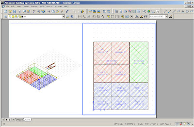
Exporting gbXML data from AutoCAD MEP

1. Open the drawing file in the AutoCAD MEP in this case.

Note: Verify that the latest version of AutoCAD MEP is installed before beginning this process. Autodesk products are updated with Live Update, which downloads patches to your product using Communication Center. Users can use Live Update to check for updates when a web connection is established. If a product patch is available, notification of its availability is received on the AutoCAD status bar, and the patch can be either downloaded directly from an Autodesk server or modified first before being copied to users' workstations.

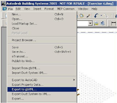
2. Go to the File drop down menu and select Export to gbXML.

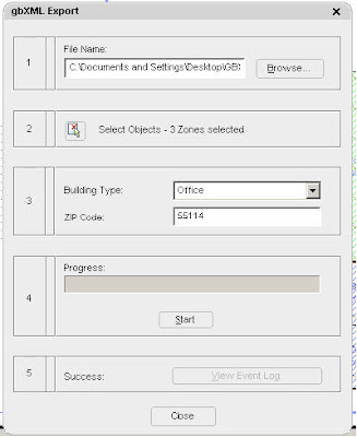
3. Select the location to export the gbXML data to, the number of zones to export, input the building type and zip code, then press the Start button to begin the export process.

4. When finished, press the Close button and exit out of AutoCAD MEP.

5. Using Windows Explorer, place the gbXML export file into the TRACE 700 Projects directory, typically this will be C:\CDS\TRACE700\Projects.


Importing gbXML data in TRACE 700

1. Open TRACE 700 and start a new file. This can be done by going to the File drop down menu, clicking on New, then TRACE 700, then entering a name for the file, and clicking on Open.

Note: Verify that the latest version of TRACE 700 is installed before beginning this process. Updates can be downloaded by going to the Help drop down menu, selecting Trane on the Web, and choosing Check for Updates or visiting the Download Center at http://www.tranecds.com/.

2. Go to the File drop down menu and select Import gbxml…


3. Navigate to the .xml file that was created during the export from AutoCAD MEP and click on Open.

Note: If errors occur during the import process please install the latest MSXML from Microsoft from http://support.microsoft.com/default.aspx?scid=fh;EN-US;sp

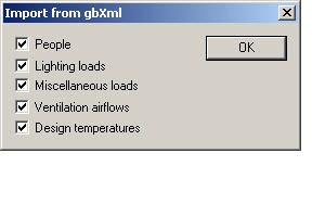
4. Select the desired information to import from the gbXML file and click OK.


5. Note any error messages that occur during the import process and click OK. Make sure to verify the inputs that relate to the error messages in TRACE input file. In this case, ventilation airflows were input in two ways in the CAD file, therefore one of the methods was selected to be used in the import.

7. Verify/refine the inputs in Create Rooms and/or use Templates to make changes in mass (see How to Use Templates.doc for details on how templates work).

Note: Due to the gbXML import, the vast majority of inputs for Create Rooms will have been filled out during the import process. Also, note that 75+ percent of the time that it takes to input a file is typically spent in Create Rooms and the gbXML import can reduce this time by more than two thirds.

8. Add additional details to the airside systems in Create Airside Systems.

Note: For details on how to model different airside systems, please refer to the TRACE 700 Modeling Guide.

9. Reassign the rooms to the refined systems in Assign Rooms to Systems (see the document Zoning in TRACE.doc for details on how to zone rooms in TRACE). From this point on, the TRACE project file will function as a typical TRACE 700 file.

Note: For details on creating cooling and heating plants please refer to the TRACE 700 Modeling Guide.

Note: For details on inputting utility rate information see How to Create Utility Rates.doc.

Exporting gbXML data from TRACE 700

1. Open TRACE 700, open the project file (filename.trc), and calculate at least the design section.

2. Go to the file drop down menu and select Export gbxml…


3. Select the existing .xml file that was used during the import process


4. When the export is complete, the information for the rooms plus zones will have been exported to the xml file.

Importing gbXML data in AutoCAD MEP

1. Open AutoCAD MEP and open the drawing file.

2. Go to the File drop down menu and select Import from gbXML…

3. Select the xml file to import that data from and click on Open.


4. TRACE 700 calculation data should now be included with the drawing file.

GbXML Results Exported From TRACE 700

  • Room
    • Space Loads - These loads can be found in the space loads section of the Room Checksums Report.
    • Cooling Skylite Solar
    • Cooling Skylite Conduction
    • Cooling Roof Conduction
    • Cooling Glass Solar
    • Cooling Glass Conduction
    • Cooling Wall Conduction
    • Cooling Partition
    • Cooling Exposed Floor
    • Cooling Infiltration
    • Cooling Lights
    • Cooling People
    • Cooling Miscellaneous Equipment
    • Cooling Ceiling
    • Cooling Ventilation
    • Cooling Over-sizing
    • Total Cooling
    • Heating Skylite Solar
    • Heating Skylite Conduction
    • Heating Roof Conduction
    • Heating Glass Solar
    • Heating Glass Conduction
    • Heating Wall Conduction
    • Heating Partition
    • Heating Exposed Floor
    • Heating Infiltration
    • Heating Lights
    • Heating People
    • Heating Miscellaneous Equipment
    • Heating Ceiling
    • Heating Ventilation
    • Heating Over-sizing
    • Total Heating
    • Coil Loads – These values come from the System Component Selection Report.
    • Main Cooling Coil Tonnage (if main cooling coil is at the room level)
    • Auxiliary Cooling Coil Tonnage (if auxiliary coil is present in system)
    • Main Heating Coil Mbh (if main coil is at the room level)
    • Preheat Coil Mbh (if preheat coil is at the room level)
    • Reheat Coil Mbh (if reheat coil is at the room level)
    • Humidification Coil Mbh (if humidification coil is present in system)
    • Auxiliary Heating Coil Mbh ( if auxiliary coil is present in system)
    • Fan Airflow – These values come from the System Component Selection Report
    • Primary Fan (if fan is at the room level)
    • Auxiliary Fan (if system required)
    • Room Exhaust Fan (user specified)
    • Diffuser

Additional questions regarding TRACE 700, gbXML, Varitrane Duct Designer, and/or ddXML should be directed to the C.D.S. Support Center - cdshelp@trane.com or 608-787-3926.