Showing posts with label Standards. Show all posts

Tuesday, December 29, 2009

Making the Transition from CAD to BIM

Electrical Construction & Maintenance
March 2009
By James Bratton, Dynalectric -- An EMCOR Co.

In today's fast-paced competitive construction market, it's no longer enough to execute a project in the real world of girders, sheet metal, pipe, and racks. These days, requests for proposals (RFPs) on most large projects now require electrical contractors to execute the project first in the virtual world using Building Information Modeling (BIM), and for good reason. Effective use of BIM can improve design, enhance constructability, and accelerate the schedule, saving time and money for the owner as well as the project team - if only BIM software came "out of the box" designed and purposed for electrical contractors.

Yet, in the experience of EMCOR Group, Inc., headquartered in Norwalk, Conn., it's well worth the contractor's time, effort, and financial investment to make the transition. In fact, successful implementation and use of BIM requires significant investments in technology, staff, and training. With more than 200 professionals who are well versed in using BIM, EMCOR and its subsidiaries have first-hand experience with this transition.

BIM is comprised of 3D modeling concepts, information database technology, and interoperable software in a desktop computer application that architects, engineers, and contractors can use to design a facility and simulate construction. The technology enables members of the project team to create a virtual model of the structure and all of its systems in 3D and share that information with the entire project team. The drawings, specifications, and construction details are integral to the model, which encompasses building geometry, spatial relationships, geographic information, and quantity properties of building components. As a result, team members are able to identify design issues/construction conflicts and resolve them in a virtual environment well before construction begins in the real world.

Customizing BIM
The saying that necessity is the mother of invention certainly applies to BIM in the electrical contracting industry. Most of the development in BIM has focused on the purposes and needs of architectural and engineering firms. The mechanical contracting industry has the advantage of real-world models of its equipment and parts via third-party vendors. Software vendors have not built a BIM product that comes out of the box with content that completely meets the needs of electrical contractors and fabricators. As written, these programs simply reserve space for the conduit.

In 2002, the Los Angeles branch of EMCOR's Dynalectric subsidiary began evaluating what was then called "Building Systems" (now AutoCAD-MEP) for use in its business, as it saw interest grow among owners and general contractors. Since that time, the company has invested considerable resources - both dollars and hours - in systems, in-house customization, and training to boost the company's capabilities.

Over the course of six years, Dynalectric developed accurate, real-world models of more than 4,000 electrical system components by taking each piece and modeling it in 3D. A layer standard was determined and keyed (e.g., a layer for conduit, layer for hangers, etc.), and the system was configured to automatically place each type of component on the correct layer. As a result, when a BIM engineer models an electrical system on a project, it is as accurate as if it were installed on the job site

Moreover, the system has been customized in-house to do everything from schedules and take-offs to automatic engineering calculations - all with the click of a mouse.
The "I" in BIM
The intelligent property database corresponds to the "I" in BIM. Intelligent property data can be extracted from the model for the purposes of engineering, take-off, and prefabrication. However, it didn't come in off-the-shelf software; Dynalectric has customized the system to enable its staff to perform these functions.

One of the main benefits of customized BIM software is being able to schedule and annotate the drawings. For example, by applying intelligent property data to conduit and parts, the staff can very quickly perform a take-off of the conduit to determine the number of linear feet or quantity of hangers. To annotate all of the conduit elevations, the system pulls live data from the actual model components in the drawing; no one has to stop and look it up.

Customization has enabled the staff to perform engineering calculations on the spot. For example, if a team member needs to calculate the load on a 10-ft section of a conduit rack, he or she clicks on it. Then, a schedule table is inserted into the drawing with the total run of 30 ft (three 4-in. EMT conduits); total load of 54.48 lb of weight per foot with copper wire and conduit; total weight of 544.8 lb; and 272.4 lb of gravity load at each anchor in each rack.

A set of routines was created that works inside of the intelligent property data to calculate strut loads, which recalculates automatically as the user changes the length of the object. This enables the staff to perform live engineering calculations and "what-if" scenarios very quickly and accurately.
Evolution of capabilities
An early milestone in Dynalectric's use of BIM was a $25-million project to upgrade the Hollywood Bowl in 2003. Designed by Hodgetts + Fung architects, the project included a reconception of the arch, advanced digital sound reinforcement system, and expanded stage with a halo-like acoustic canopy.
Dynalectric used BIM to model 25,000 ft of conduit running through a complex "forest" of structural steel. Although the electrical BIM model was complex, it was still a rudimentary conduit model by today's standards. Yet, it was only through the use of BIM that the electrical contract could have been effectively planned and executed. Using 2D sections and elevations to try to understand the structure in the traditional method would have made it nearly impossible to effectively find a routing for all the required systems.

In 2005, Dynalectric was still the only contractor using BIM on the new Four Seasons Hotel and Spa Westlake Village, Calif., which was designed by WATG architects for owners Castle & Cook, Inc. More than 750,000 ft of conduit and support systems were routed for this six-story, 476,000-sq-ft structure, which includes 268 guest rooms, a spa, wellness center, TV studio, clinic, and conference center.

The Dynalectric team began by looking at the primary electrical service that was entering the main electrical room. The single line specified (20) 4-in. conduits for the two 4,000A primary feeds into the building. These raceways were routed to an already undersized and overcrowded electrical room. By modeling this area, the team was able to quickly identify the problems and clearly demonstrate the issues to the designers. For example, the staff suggested replacing more than 13 sq ft of conduit with 1.2 sq ft of busway, freeing up a large amount of space in an already congested space at no additional cost.

It is also noteworthy that more than 3,500 anchors were embedded into the structure for conduit support systems. Due to the accuracy of the model, Dynalectric was able to use 99% of these anchors.

Virtual best practices
BIM is much more than an electronic drawing tool because it allows team members full collaboration. In the best of all worlds, the general contractor (GC) is engaged in designing and implementing the BIM execution plan. This includes determining what will be modeled and at what level of detail (which varies from project to project), and facilitating mechanical, electrical, and plumbing (MEP) coordination. As every contractor knows, coordination is a give-and-take process, especially when the project is using the traditional design-bid-build delivery method, in which post-bid changes incur additional costs for the contractors.

Here's how it works in the BIM world. Each trade receives architectural and structural models from the owner. Then the trades begin routing their systems. Weekly, each trade contractor posts its systems to an FTP or other shared Web site. Typically, the GC assembles all of the models into a composite using NavisWorks Review or Manage, which enables project team members to integrate and share data and drawings from various software programs.

The composite BIM can be viewed, manipulated, and analyzed for clashes among the trades, who negotiate changes to resolve the clashes. This process continues floor by floor and quadrant by quadrant until everything finally "fits" in the virtual building.

The Miller Children's Hospital's Pediatric Pavilion at Long Beach Memorial Medical Center, completed in 2007, is a good example of this concept. It illustrates the process of a BIM-coordinated project in which the GC (Turner Construction) did an outstanding job of creating a partnered environment among project team members. As designed by the architects, the Pediatric Pavilion is a 129,000-sq-ft acute care addition with seven operating rooms, a new pediatric imaging center, 48 neonatal intensive care beds, and 24 general pediatric beds, plus a 5,500-sq-ft central plant.

At the onset of the preconstruction phase, the GC brought all of the players together to assess their capabilities, determine what would be modeled, and decide what level of detail would be produced. A CAD standard and procedures were clearly defined early on in the process, including drawing naming conventions, discipline-specific layer colors, file-sharing procedures, file origins, and model detail.

Turner Construction brought the steel subcontractor on early enough in the project so that its fabrication model was available to the coordination team. This was of critical importance to the success of the project. Normally, MEP contractors must create this from the contract structural drawings. This information is rudimentary, at best, and is only intended to convey the design intent to the fabrication contractor. By the time the fabrication contractor completes his design, many requests for information (RFIs) are processed, and the model is significantly different than what was conveyed in the original design documents. The fabrication model will contain bracing and connection plate information that is not available until their model is detailed and completed. This usually impacts MEP trades significantly at a stage in the job when it is too late to mitigate problems in a cost-effective manner.
The GC also provided accurate internal/external wall and deck models, which enabled all of the MEP detailers to work from the same data set of information, reducing interpretation errors and increasing subcontractor productivity. Thanks to realistic scheduling by the GC, the project team avoided another common mistake: under-allocation of time for preconstruction. On the Miller project, the team had approximately eight months of preconstruction prior to any deliverable milestones.

Furthermore, the GC remained engaged as an active facilitator throughout the process, handling mediation of conflict resolution, management and tracking of weekly clash detection, bringing in the design team when appropriate in order to expedite information flow, coordinating schedule management, and facilitating contractor engagement with the use of NavisWorks and interactive whiteboards in the coordination meeting room.
The project was completed using the best practices of BIM and virtual construction, resulting in an efficient and productive process and a highly successful project for all involved.

Making the transition
As noted above, successful implementation and use of BIM requires significant investments in technology, staff, and training. There is no "cookie-cutter" solution. That's why going into the process with your eyes open is essential. It is not likely that there will be software that is purposed for the electrical contractor in the very near future. Be prepared to carefully evaluate the software you are considering buying. Analyze your goals, set your priorities, and start working in that direction. At the very least, making the transition from CAD to BIM requires more powerful PC hardware and new software, along with a network, servers, and high-speed telecommunications backbone that support the process. Then, it requires a considerable investment in customizing the application software. Commitment from upper management also is a must. Without their support - both financially and ideologically - moving forward into BIM will be difficult, if not impossible.

The transition also requires a transition in terms of staffing. It takes someone with a foundation of computer skills, a willingness to learn BIM technology and the process of collaboration, and the technical and intellectual capabilities to integrate this knowledge into the electrical contracting business. To become an effective building information modeler, it is not enough to understand the software. To build a virtual electrical system, one must first have considerable experience and success building them in the real world.
That is why EMCOR selected field people who have 20-plus years of electrical installation experience and an aptitude for BIM to model these systems. The mentoring approach is the best way to train people on BIM. The basic process is to give them AutoCAD classes then one-on-one 3D training. Next, they work on projects side-by-side with experienced BIM people who transfer all of the knowledge they need to work on their own. Finally, after approximately two years, they are ready to perform BIM on their own.

Although it's a long and expensive process, the benefits of BIM are worth the investment. When BIM is effectively used, it coordinates MEP trades, expands prefabrication opportunities, eliminates rework, increases productivity, decreases labor costs, and improves the consistency of the work product. BIM is no longer the future of electrical contracting - with most owners and GCs requiring this capability, especially on large projects, the future is now.
Bratton is engineering manager, virtual design and construction, in the Los Alamitos, Calif., office of Dynalectric Los Angeles - an EMCOR Co. He can be reached atJbratton@kdc-systems.com.

Monday, March 17, 2008

How to best place Addenda, Alternates, or As-Builts within the project?

How you organize these items would largely depend on your internal processes and workflow. One solution would be to draw the alternates as regular constructs in Project Navigator and then create special views for them.

If you want to present completely different plans/elevations to represent Alternates, you could use divisions in Project Navigator to represent them; when generating the view, you just need to include the appropriate division into the view.

In some cases you might also consider copying the project in Project Navigator and put the Alternates into the copied project. If you copy a project, however, you have two different file sets to maintain; the copied project does not retain any links to the original one.

Monday, October 16, 2006

ABS Based on Applicable Building Codes and Equipment Specs


An important Whitepaper written by Autodesk describing how AutoCAD MEP meets industry standards in its program.

Download Whitepaper Here

Introduction
Engineering designs must meet strict guidelines and codes to ensure that structures are safe and economical for the public and to maintain design consistency throughout the industry. AutoCAD MEP software enables engineers to create an object-based systems model that follows industry standards. Whether you’re using the duct sizing tool, placing a piece of electrical equipment, or sizing a sanitary main, AutoCAD MEP helps ensure that your data is based on applicable codes and guidelines or on equipment specifications from leading manufacturers. This white paper shows how the codes, guidelines, and equipment specifications built in to MEP software can help you improve accuracy and ensure that your designs meet industry standards.

HVAC Ductwork and Piping
Take a look at the guidelines that influence the development of ductwork and piping design tools within AutoCAD MEP and compare them with the way you design today. Feeling confident with your engineering design is what it’s all about.

Duct Sizing Calculator
Designers who have sized ductwork are probably familiar with the Trane Ductulator tool—that handy little cardboard square with the rotating circle in the middle. In fact, most engineers have customized the tool by marking the design criteria they use most often. Engineers rely on this duct-sizing tool because it is based on equations derived from the industry-benchmark ASHRAE (American Society of Heating, Refrigerating, and Air- Conditioning Engineers) standard.

The AutoCAD MEP duct sizing tool is derived from the same standard, ASHRAE Fundamentals Handbook 1997, and can be found in the Add Duct dialog box. From this dialog box you can select the system type (supply, return, exhaust, and so forth), enter the airflow (CFM), and choose the Calculate button. If you are routing round ductwork, calculate the diameter. If your design calls for oval or rectangular ducts, calculate either the width or the height. And as with any MEP tool, if you’re not satisfied with the calculated result, you can simply select a different size.

The design criteria you specify for duct sizing is linked to the system type chosen. To specify that criteria, choose the HVAC System Definition. Select a system type, and then select the Design Parameters tab. Here you can decide whether to size your ducts for this system based on air velocity or static pressure drop per 100 feet of duct. You can also determine a roughness coefficient as well as air density. Being able to specify these parameters per system type is helpful. For example, you can create a low-pressure supply duct system and a medium-pressure supply duct system and use different sizing parameters for each. This is just like marking your Ductulator at .08 inch per 100 feet for low-pressure ducts and at 0.3 inch per 100 feet for medium-pressure ducts.

HVAC Load Calculations and Duct Sizing
One of the first tasks assigned to new HVAC designers is running a load on a building. Performing this task gives engineers-in-training their first look at what goes into a building load calculation and how those components affect their design, such as building construction, people densities, outdoor air requirements, equipment loads, lighting loads, building zones to optimize equipment loading, building orientation, and much more. Manually transferring this data to load calculation software can be tedious and prone to errors.

AutoCAD MEP helps eliminate costly errors by enabling designers to transfer data from the building model directly to engineering analysis applications like Trane’s Trace 700, IES, Varitrane Duct Designer, or Elite Ductsize. Use standard file formats, such as gbXML and ddXML, to directly import building design data. Once the design data has been transferred, use Trace 700 to perform heating and cooling load analyses, and Varitrane Duct Designer and Elite Ductsize to calculate optimal duct sizes using the static regain, equal friction, or constant velocity method.

HVAC Equipment—MvParts
Equipment location is an integral part of any HVAC design. Coordinating space requirements, function, and ease of maintenance for each piece of equipment is essential for its placement. Equally important is ensuring that systems don’t conflict with other equipment or structural components in the design.

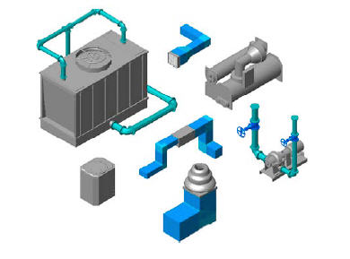
AutoCAD MEP provides an extensive catalog of equipment made up of MvParts. Each piece of equipment has intelligent connection points for fast and easy connections to ductwork, piping, electrical conduit, and more. MvPart objects also have the ability to check for interferences with other components in your design, making it easier to coordinate your mechanical rooms, electrical rooms, chases, and above-ceiling space.

The nonproprietary equipment specifications provided in AutoCAD MEP are based on equipment offerings from leading manufacturers. Dimensions and connection sizes are matched against several different manufacturers, and the most relevant data is used. For example, Trane and Carrier both offer packaged rooftop air conditioning units. The dimensions for length, width, and height of the equipment casings are similar for comparable tonnages but not exactly the same. For similar units such as these, Building Systems uses the largest dimensions.

Ducts and Fittings
Most HVAC engineers have had to either write or edit a ductwork and fittings specification that references ASHRAE and SMACNA. AutoCAD MEP ductwork and fittings are based on the ASHRAE Duct Fitting Database (1994), the Round, Rectangular, and Oval Duct Industrial Construction Standards published by SMACNA, and are augmented by offerings from the leading manufacturer of duct and duct fittings in the United States (and primary author of aforementioned standards).

Pipe and Fittings
Traditional methods of creating double-line HVAC piping drawings are time consuming and inaccurate. Using standard CAD tools, engineers offset simple lines to nominal pipe sizes and frequently use a box or bowtie symbol to represent various valves and appurtenances. Nominal pipe sizes, loosely related to the actual pipe dimensions, are used for convenience, with elementary symbols representing more complex objects, such as valves and gauges, to save time. Often these symbols are not drawn to the actual sizes of the piping components they represent and can result in costly change orders in the field.

AutoCAD MEP can help reduce drawing inaccuracies and coordination issues because all pipes and pipe fittings are based on widely recognized standards, codes, and offerings from leading manufacturers. Pipe identification, outer dimensions, and nominal dimensions are referenced against ANSIB36.19, and ANSI B36.19 as published in Crane’s Technical Paper No. 410. For example, using Building Systems, draw a piece of 6-inch diameter, schedule 40, carbon steel pipe with flanged connections (apply Building Systems Floor – 2 Line Display). Now check the outer dimension of the pipe. Even though you drew a 6-inch nominal size diameter pipe, you get the actual ANSI-specified outer dimension (6 5/8 inch) for that particular type of pipe, resulting in a more accurate design.

Pipe fittings are referenced against various applicable standards:
● Flange: ANSI/ASME B16.5
● Socket Weld and Threaded: ANSI/ASME B16.11
● Cast Iron: ANSI/ASME B16.12 and 16.13
● Butt Welded: ANSI/ASME B16.9
● Grooved: Not described in standard, based on offering from leading manufacturer
● Brazed: ANSI/ASME B16.18, B16.22, B16.23, and B16.29 among others

Plumbing
Plumbing design relies heavily on code requirements for sizing domestic water, sanitary sewer and ventilation pipes. Why not use an application that can incorporate the code requirements your company follows directly into its design tools.

Plumbing Fixtures—MvParts
Traditionally, architects have located the plumbing fixtures in their designs. Now that the connectivity of AutoCAD MEP objects can span the xref barrier, plumbing engineers and designers can place toilets, urinals, sinks, and more in architectural drawings. For effective use, these fixtures must be based on leading manufacturers’ offerings so that dimensions and sizes can be trusted. That’s exactly what Autodesk
Building Systems does. Whether you’re placing a floor drain, drinking fountain, toilet, or lavatory, Building Systems helps to ensure that the plumbing fixtures in your designs match industry standards.

Plumbing Pipe Sizing
In the past, sizing plumbing piping required thumbing through page after page of code. AutoCAD MEP alleviates the tedium by providing sizing tools for supply water piping and sanitary piping based on the Uniform Plumbing Code–2000, Crane’s Technical Paper No. 410, American Society of Plumbing Engineers (ASPE) chapter interpretations, and engineering judgment.

A typical method for sizing water piping is to tally the load values based on a fixture count, convert that fixture unit count to gallons per minute (GPM) requirement, and use a diagram that illustrates the relationship between GPM, pressure drop per 100 feet, and fluid velocity. Assuming the pressure loss through taps, tees, valves, and other appurtenances has been accounted for and compared to available water pressure, a pipe size can be obtained from the diagram. However, performing this process manually can be tedious and time consuming.

AutoCAD MEP simplifies this process by providing a load demand table based on Uniform Plumbing Code 2000. You can easily edit this table or create a new one to meet your company’s requirements. With the fixtures in place and the water piping connected, you can then use the supply pipe sizing calculator. Use the Size Supply Pipe dialog box to modify different factors affecting pipe sizing, such as fluid velocity (feet per second), available pressure (psi), and pressure at highest fixture (psi). It also includes a customizable pipe sizing table that provides equivalent length data for various fittings. Other data fields in the dialog box are populated when you have selected a pipe segment to size. The software calculates a pipe size using the Hazen-Williams friction loss formula and a derivation of the Hunter’s Curve referenced from ASPE.

AutoCAD MEP also provides a sanitary pipe sizing calculator, which extracts the fixture units connected to the pipe segment being sized and compares this value to maximum permissible load data stored in the sanitary pipe sizing table. The load data is further categorized as stacks, branches, or offsets to accommodate different design conditions. The sanitary pipe sizing table, like the fixture unit table, is based on Uniform Plumbing Code 2000. Customize this table or create a new one to reflect the codes and standards your company follows.

Fire Protection
AutoCAD MEP fire protection content was created using industry standards. Customize your fire protection designs by taking advantage on “in-the-box” content design tools to create more equipment on the fly.

Fire Protection—MvParts
Like other engineering equipment included in AutoCAD MEP, the equipment provided for fire protection is based on specifications from leading manufacturers. Equipment includes wet and dry sprinklers, various types of hose cabinets, fire department connections, hose connections, applicable valves, and tanks. Fire protection equipment is included with Mechanical MvParts.

Fire Protection Pipe and Fittings
With AutoCAD MEP, add fire protection pipe and fittings to your design using the Add Pipe command for HVAC piping. Since both disciplines use virtually the same types of pipes and fittings, the standards and guidelines referenced in the HVAC Pipe and Fittings section apply here as well.

Electrical
Electrical designs require code compliance. Use Building Systems electrical design tools with confidence knowing that your construction documents meet the requirements set forth by code officials and local authorities.

Electrical Wire Sizing
Looking up wire sizes manually in the National Electric Code ampacity tables is a tedious and time-consuming job. AutoCAD MEP automates that process. To use wire sizing, you first draw the wiring, associate it with a circuit, and designate a wire style. If no wire style is specified for the circuit, the wire cannot be sized. The circuit must be assigned because the conductors are sized based on the circuit rating. With the necessary values in place, Building Systems retrieves wire sizes from the ampacity table in the wire database (ampacity.mdb). This table is arranged in much the same way as the National Electric Code table 310-16. It includes columns for ground conductor sizing for both copper and aluminum conductors, similar to the table in section 250-122 of the National Electric Code. An additional table (ambients.mdb) contains correction factors ased on ambient temperatures specified in National Electric Code 310-16. These tables rovide the information required for accurate wire sizing and are fully customizable using icrosoft® Access.

Electrical—MvParts
AutoCAD MEP includes a wide selection of electrical equipment based on specifications from leading manufacturers. The electrical MvParts catalog includes equipment such as transfer switches, motor starters, termination boxes, variable frequency drives, and emergency power generators. Providing intelligent connections and enhanced properties, electrical MvParts can be easily integrated into your designs. If you’re accustomed to specifying equipment from a manufacturer that is not included in Building Systems, you can create that content using the Content Builder—a feature that has come a long way since earlier releases. In just a few steps, you can create large catalogs of equipment quickly and easily. Before creating custom content, however, check out the manufacturer’s website to see if they offer the equipment you need. Many manufacturers have already created MvPart catalogs of their equipment, which you can drag into your design using i-drop® technology.

Electrical Devices
Electrical devices are the primary graphical objects used in electrical drawings. Generally schematic in nature, they can contain additional 3D blocks as part of the object, which makes them useful for interior elevations and interference detection with other building systems objects such as ductwork and piping. The connectors for electrical devices are different from the connectors for MvParts and are created using the Style Manager. Electrical devices modeled as symbols have been developed using the same standards as symbols. And if they contain 3D elements, they are referenced against data from leading manufacturers.

Electrical Panels
Electrical panels are similar to electrical devices but do not have connectors. They are an integral part of electrical designs created with AutoCAD MEP because circuits cannot be created without them. Although you can draw the wiring, the circuit it represents will not exist. The panels that ship with AutoCAD MEP are model-based parts that are referenced against offerings from leading manufacturers where appropriate, but are mostly generic. You can easily create new panel types through the Style Manager to meet the specifications of the manufacturer you choose.

Electrical Conduit and Cable Tray
The 3D components of conduit and cable tray are useful when coordinating clearances above ceilings, determining space constraints in electrical equipment rooms, and checking interferences with ductwork and piping. The most commonly used standards are NEMA FB 1 for conduit and NEMA VE1 – 1998 for cable tray. AutoCAD MEP uses these standards for conduit and cable tray content.

Symbology
Companies doing engineering design work need to establish drafting standards. AutoCAD MEP incorporates the most common standards and guidelines used in the industry. Many of the original symbols used in AutoCAD MEP software came from Softdesk® 8, which were referenced to various AMSI and ISO guidelines. In addition, symbols included many user requests for specific images that may or may not have met various code requirements. These symbols were matched against the ASHRAE Fundamentals Handbook, Chapter 34, Abbreviations and Symbols, the AIA Architectural Graphical Standards, and the SMACNA CAD Standard. However, not all symbols have a match in these standards. All new symbols added to AutoCAD MEP meet specific applicable codes such as NFPA 170 – 2002.

Connector symbology for single-line piping such as grooved, welded, threaded, bell and spigot, brazed, flanged, glued, and socket welded were referenced against the National CAD Standard and ASHRAE Fundamentals Handbook. A few of these connectors were not described in either of these standards, so graphics were based on alternate resources such as data from leading manufacturers.

Template Content and Styles
Establishing template content and styles based on your current design practices sets you on the path of increased productivity. Once your standards have been incorporated into the software, you’ll find that creating model-based designs doesn’t get any easier.

Templates
Template content and styles in AutoCAD MEP cover everything from duct and pipe system types to electrical voltage definitions. You can customize templates to meet your company’s requirements or get started quickly out of the box with the default templates that ship with the software. For example, without using one of the electrical templates the values that are stored for electrical preferences would not exist. Voltage definitions would be undefined, requiring you to create them manually. Without specifying voltage definitions, you could not add circuits to the drawing. The template content comes from a variety of sources, including but not limited to the Uniform Plumbing Code, the National CAD Standard, the SMACNA CAD Standard, ASHRAE Fundamentals Handbook 1997, National Electric Code, ASPE Data Books, engineering judgment, and, most important, the AIA Architectural Graphic Standards.

System Definitions
Various system definitions are provided in the templates for each of the disciplines: HVAC, plumbing, and electrical. Based on different reference materials and guidelines, engineering judgment was used to determine the different system types available out of the box. The important thing to note about system definitions is that you’re not limited to the examples provided in AutoCAD MEP. These system definitions were offered to help you start designing quickly and to serve as examples of how to create other system types. Once you’re familiar with Building Systems software, you can create and customize system types as needed.

Labeling Standards
Labeling engineering designs manually is a tedious and time-consuming task. AutoCAD MEP automates much of the annotation. From labeling a rectangular duct size to automatically tagging an electrical device upon insertion, your productivity increases and your design accuracy improves. Because labeling is not standardized across the industry, many of the labeling styles are based on engineering judgment. And like most Building Systems design tools, annotation is highly customizable so you can meet your company’s unique needs.

Conclusion
AutoCAD MEP is easy-to-use design software that increases productivity, enhances collaboration among design team members, and improves workflow efficiencies using an object-based systems model. Building Systems improves on existing methods for creating construction documentation while supporting traditional design requirements. The most widely accepted engineering codes, standards, and guidelines have been incorporated into AutoCAD MEP to help ensure that your designs meet industry standards. Furthermore, all tables, symbology, system settings, and values can be customized as necessary to meet the requirements of your organization, while still meeting industry requirements.