Wednesday, January 23, 2008

IFC Import to AutoCAD MEP

When you import an IFC file, drawing files are created that correspond to each part of the IFC project structure. The files will be xrefed together into a main host file that represents each part of the file structure in the IFC file.

In some instances, you may need to turn on some display components for them to display after you import an IFC file, such as surfaces of spaces.

Importing IFC files result in the drawing files being organized at the same level.

When you import an IFC file, you specify a name for the top level drawing that is created from the IFC file. This drawing contains xrefs only. For example, importing an IFC file and naming it Small Office Building, creates a DWG called Small Office Building.dwg that contains all of the xrefs that correspond to each part of the project structure contained in the IFC file. During import:

  • A site drawing is created if the IfcSite exists in the IFC file. This file is created using the top level drawing name with the IfcSite name appended and is referenced into the top level drawing. If there was no site name specified in the IFC file, no site drawing is created.
  • A building drawing is created using the top level drawing name with the IfcBuilding name appended. This file is xrefed into the top level drawing. (Please note that AutoCAD Architecture uses the Project Name from the Export to IFC dialog as the IfcBuilding Name. This is noticeable if you are importing an IFC file that originated in AutoCAD Architecture.) Using the Small Office Building example above, the drawing name would be Small Office Building-Commercial Project.dwg because Commercial Project was the IfcBuilding name in the IFC file.
  • A Storey drawing is created for each IfcStorey contained in the IFC file. The files are created using the top level drawing name with the name of the IfcStorey appended. These files are referenced into the project file.

AutoCAD MEP IFC Export To Revit

Based on established, international standards for common objects in the building industry, the Industry Foundation Classes (IFC) file format provides an interoperability solution between different software applications for reducing the loss of information when files are transmitted.

AutoCAD MEP is IFC-certified for importing and exporting version 2x3 IFC files. IFC files from versions 2x2 and 2x can also be imported if the data is compatible with 2x3 and is consistent with implementation agreements as defined for the IFC 2x3 coordination view.

IFC certification enhances your ability to share project information across disciplines and technical applications over the life of the project. For example, building models drawn in AutoCAD Architecture are saved to a DWG file format. You can export the drawing using the IFC format to an IFC-certified application that could not otherwise open a DWG file like Revit. Likewise, you can import an IFC file that was in a format like Revit and work on that drawing in AutoCAD MEP

When you export a drawing to IFC, a file is created with information you specify for project name, project number, location of the file, and any external references (xrefs).

The IFC file structure at export is hierarchical with 4 defined levels as shown.
Even though the IFC file structure is not visible in AutoCAD MEP, it governs the files created when an IFC file is imported.

To see how to import this IFC file into Revit, go to my Revit MEP blog at www.revitmep.blogspot.com

What is gbXML?

The Green Building XML schema, referred to as “gbXML”, was developed to facilitate the transfer of building information stored in CAD building information models, enabling integrated interoperability between building design models and a wide variety of engineering analysis tools and models available today. Today, gbXML has the industry support and wide adoption by the leading CAD vendors, Autodesk, Graphisoft, and Bentley. With the development of export and import capabilities in several major engineering modeling tools, gbXML has become a defacto industry standard schema. Its use streamlines the transfer of building information to and from engineering models, eliminating the need for time consuming plan take-offs. This removes a significant cost barrier to designing resource efficient buildings and specifying associated equipment. It enables building design teams to truly collaborate and realized the potential benefits of Building Information Modeling.

XML, extensible markup language, is a type of computer language that allows software programs to communicate information with little to no human interaction. This approach allows building designers to focus on what they want to do most - design beautiful, environmentally responsible buildings that use intelligent technologies to meet their client's needs at the lowest cost possible. Helping realize the promise of Building Information Modeling, gbXML allows intelligent solutions for the design, certification, operation, maintenance, and recycling of buildings.

Building Energy Analysis Programs that work with gbXML

Arup
EnergySave - An easy to use intelligent interface to Arup's Energy2 building energy analysis program.
CADLine
Cymap – An integrated building services design suite, covering both mechanical and electrical. Imports gbXML building data for use in services design, energy analysis and demonstrating compliance with Building Regulations.
Carmel Software
Loadsoft 6.0 - Loadsoft 6.0 from Carmel Software is a commercial and industrial HVAC load calculation software package that is based upon the ASHRAE 2005 Fundamentals radiant time series (RTS) method.
Carrier
HAP (Hourly Analysis Program) - HAP is a dual function program - full-featured load estimating and system sizing for commercial buildings plus versatile hour-by-hour energy and operating cost analysis.
Department of Energy - National Renewable Energy Laboratory
Energy-10 - A PC-based building energy simulation tool that helps architects and building designers quickly identify the most cost-effective, energy-saving design alternatives for small commercial and residential buildings that are less than 10,000 ft².
Environmental Design Solutions Limited
Tas - Tas Building Designer simulation software from EDSL (www.edsl.net) is a new generation product, no old legacy code to slow you down. Try it for room load and plant component sizing, energy use and running costs, CO2 emissions, natural ventilation and passive design with solar shading.
Green Building Studio, Inc.
Green Building Studio (GBS) - A building energy analysis web service designed for easy integration with existing 3D-CAD/BIM software tools. Below are files that are produced by the GBS.
DOE-2.2 - One of the most advanced and widely used building energy analysis engines.
EnergyPlus - The successor to DOE-2 that has advanced building analysis capabilities.
eQuest - The most widely used graphical building energy analysis tool in the world.
VRML & X3D - Virtual Reality Modeling Language and its XML version used for describing 3D environments.
IDEA Server® - A sophisticated and easily integrated web-based building energy analysis solution. Below are engines that are supported by IDEA Server.
DOE-2.1e & DOE-2.2 - Two of the most advanced and widely used building energy analysis engines.
IES Limited
IES - The IES, is a unique, integrated system for building performance assessment that bring productivity and excellence to every aspect of building design.
Trane
TRACE® 700 - A comprehensive and widely used energy and economic analysis tool for mechanical engineers.
National University of Ireland, Cork, Cylon Controls ltd., & Ace Controls ltd.
Development of a generic web based software tool that integrates standard building management systems and third party auditing applications.

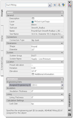
Specifying ASHRAE Fitting Types in AutoCAD MEP 2008

Use this procedure to assign ASHRAE identification numbers to duct fittings in a duct system. You can assign ASHRAE numbers to fittings by using the Properties palette, or by using the Modify Fitting ID dialog in the event log of the Duct System XML Export dialog.

The American Society of Heating, Refrigerating, and Air-Conditioning Engineers (ASHRAE) publishes a database that includes loss coefficient tables for many duct fittings. Each duct fitting in the database is identified by a unique number. The external tool you use to analyze your system may require that all fittings in the system are assigned an ASHRAE fitting number.


To specify an ID in the Properties palette

  1. In the drawing, select the fitting that you want to specify. To specify all fittings of the same type in the drawing at once, select one fitting, right-click, and click Select Similar.

  2. On the Properties palette, expand Advanced, and expand Engineering Data.

  3. In the Assigned Engineering ID drop-down list, view the available choices, if any, for ASHRAE fitting numbers. If the ASHRAE number you want to use is in the list, select it for Assigned Engineering ID.

  4. If there is more than one ASHRAE number to choose from, consult the ASHRAE Duct Fitting Database to make sure you choose the most appropriate fitting for your system. Some fittings are dependent on flow direction or duct system type, such as supply or exhaust.

  5. If the ASHRAE number you want is not in the list, or there are no numbers listed, enter the ASHRAE fitting number for Assigned Engineering ID.

  6. Right-click, and select Deselect All.

  7. Continue specifying fittings, if necessary.


To specify an ID when exporting to duct system XML

  1. After exporting a duct system for analysis, click View Event Log in the Duct System XML Export dialog.

  2. If there are any error warnings for multiple fitting IDs in the Event Log, select the warning, and click (Modify Fitting ID).

  3. In the Modify Fitting ID dialog, specify an ID in the Fitting drop-down list, or enter a fitting ID, and click OK. This ID is assigned to the fitting in the drawing. Repeat as necessary to resolve all fitting ID warnings. If desired, you can run the duct system export again to include the revised fitting IDs.

Monday, January 21, 2008

AutoCAD MEP 2008 Subscription Content Extensions

More AutoCAD MEP Content!

If your AutoCAD MEP is on subscription, you can download the new AutoCAD MEP Subscription Content Extension from your subscription website which provides some new mechanical, electrical, plumbing and piping content for AutoCAD MEP 2008. The download is a self-extracting installer that will install the new content as appropriate according to your product installation.

Download #1: Subscription MEP Content Extension for AutoCAD MEP 2008 - US Imperial & US Metric: This is the .exe file of US imperial and metric content for AutoCAD MEP 2008.

Below is a list of parts types added to both the US Imperial and US Metric part catalogs.

MvParts\Electrical
  • Starter
    Controllers
    Interface Stations

MvParts\Mechanical

  • Aeration Disc Diffuser
    Blowers
    Centrifuges
    Classifier
    Conveyors
    Gates
    Heat Exchangers
    Mixers
    Pumps
    Screen
    3-Way Valves
    Air Valves
    Backflow Preventers
    Ball Valves
    Butterfly Valves
    Check Valves
    Cone Valves
    Diaphragm Valves
    Gate Valves
    Globe Valves
    Knife Valve
    Mud Valves
    Valve Actuators

Pipe

  • Buttweld Cross
    Buttweld Elbows
    Buttwled Reducer
    Buttweld Tee
    Buttweld Laterals
    Flanges
    Flanged Cross
    Flanged Elbows
    Flanged Reducer
    Flanged Tee
    Flanged Laterals

As you prepare to install the content extension, keep these points in mind:

Backup all Custom Files
Back up all custom parts, including the .dwg, .xml and .bmp files.

Installation Location
The content will be added to the MEP Catalog Content location specified during the original install of AutoCAD MEP 2008. The default location is:

C:\Documents and Settings\All Users\Application Data\Autodesk\ACD-MEP 2008\enu\Aecb Catalogs.

Note: If you have moved your catalogs after installation to a new location the Content Extension parts will not be installed to the new location.

After Installation
After the content extension is installed, you will need to Regenerate your Catalogs. Once the Content Extension is installed you will be will be notified in AutoCAD MEP 2008 to regenerate the Mvpart and Pipe catalog. The regeneration of the catalogs is required to properly view and insert the addition parts.

Tuesday, January 01, 2008

Managing RAM Memory in AutoCAD MEP

A friend of mine (Tony Isenhoff of Eppstein Uhen) and I were discussing how RAM is utilized by Autodesk applications. As you work in your application, RAM is used, and in many cases is not returned to the OS when it's no longer needed. The problem arises when you start to reach the 2 GIG limit for a Process in 32 Bit Windows or you simply start to run low on memory when you are working on large projects.

But if you simply Minimize the application window, wait a second or two then Maximize your application, the RAM is given back and you can continue working.

Tony confirmed this in Revit by opening one of their larger projects using Revit Architecture, and opened 3-4 views, and watched the memory usage go up, then minimized. Below are the results:

Before minimize:


After minimize:


I also confirmed this in Revit MEP and AutoCAD MEP.

So when working in AutoCAD MEP and you get a message that you're running low on memory, try minimizing the application window!

We always knew that having multiple views open can also affect performance, but we were pretty surprised at actually how much RAM is used.


One view open: 784,380 k
Two views open: 817,520 k
Three views open: 847,220 k
Four views open: 872,896 k

So closing views that are not being used is also very important.

AutoCAD MEP 2008 is not backwards compatible

AutoCAD MEP 2008 and AutoCAD Architecture 2008 is not backwards compatible with older versions of ABS and ADT. When you perform a save as, and save back to an older version, that only saves AutoCAD objects, and not MEP or Architecture objects. The 2008 objects will give errors when opened in 2006 even after the save as was performed.

When you perform an Export To Autocad command, it breaks all of the 2008 MEP objects down to 3D solids and there will no longer be MEP or Architectural objects. Now AutoCAD and older releases of AutoCAD MEP can read them without getting errors, but the drawing no longer has the intelligence or data attached to the drawing.

Object enablers only work for programs of the same version, of different verticals such as Architecture, Civil or plain AutoCAD.

If you install AutoCAD MEP 2008 or AutoCAD Architecture 2008 and open and saved a 2007 ABS/ADT drawing, users of ABS/ADT 2007 will no longer be able to open the drawing without getting ARX errors now. In order not to get the ARX errors in ABS/ADT 2007, the drawing will need to be broken and converted to autocad solids. Because it is not backwards compatible, you will only be able to view the MEP or Architectural objects after an Export to AutoCAD has been done. Door, walls and windows will now be just 3D solids, and not doors, walls and windows.

Vertical programs like Architecture and MEP are not backwards compatible like AutoCAD is. It is a big misconception with our customers and we're trying to educate them on how the drawings behave before they ruin some of their production drawings. I have run into this many times in the past, and have been trying to spread the word. There are ways that older ABS/ADT versions can view the 2008 format drawings, but not in it's original or intended format.