Wednesday, July 30, 2008

Calculation of pipework system volumes and displaying in schedule

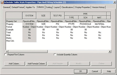
This tip will enable the user to automatically calculate the volume of pipework in a system, and display it in a schedule which will update itself to reflect any changes made to the system. First of all you have to make sure that you only select pipes when creating a schedule to calculate volumes, as fittings such as reducers will not allow the formula to work (having two sizes and no actual length specified).This will produce a schedule of just pipes, as expected. You will be presented with a schedule of question marks to begin with so you need to select the schedule, right click and select “add all property sets”. Now you need to add your formula column: select and right click the schedule and select “edit schedule table style”. Then pick on “add formula column”.


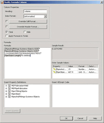
You will then see the “modify Formula column” dialogue box as shown:


You will need to set all of the options as shown above, and add the formula as shown. (The highlighted parts of the formula are selected from the “insert property definitions” box below.)

Once done, if you pick OK and then OK again, your schedule should have a column added to it showing volumes (in litres) for all pipes and a total volume at the bottom.


For other units of volume e.g. cubic metres you simply need to change the ratio currently set as 0.000001 in the formula. Of course this will only ever show volumes for the pipework only and not the fittings, so you may need to add a percentage to it for a more realistic figure.

http://www.autodesk.co.uk/adsk/servlet/item?siteID=452932&id=9997264&linkID=10427447

Saturday, July 26, 2008

AutoCAD MEP 2009 Service Pack 1 Released

Download the AutoCAD MEP 2009 Product Update 1 32-Bit Here

Download the AutoCAD MEP 2009 Product Update 1 64-Bit Here

Primary Issues Resolved by This Update
General Updates to AutoCAD MEP
The following issues have been fixed in AutoCAD MEP 2009 Update 1:

Catalog Editor

  • Unable to Write Check Permissions error occurs when copy and paste parts into the same catalog.

Duct

  • Duct sizing does not always provide the expected size when using Metric units

Electrical

  • Power Totals tool does not always state the correct load.

Pipe

  • Pipe segments will be offset from each other when using justification which is not Center/Center.
  • Insulation will not be applied to pipe fittings when using the match properties.
  • In some instances pipe object are not visible until a regenerate is performed.

MvPart

  • Invalid Enum Map String error when using MvPartModify on a multi-view part created via MvPartConvert command.

System

  • AutoCAD warning message when saving an External Reference.

Problems in AutoCAD MEP Reported with the Customer Error Reporting Utility
As a result of detailed information from customers who used the Customer Error Reporting Utility, a number of problems were identified and fixed. Updates have been made in the following feature areas:

  • External Reference (xref) Editing
  • Device Selection
  • Project Navigator
  • Multi-View Part Modify
  • Opening Legacy drawings

General Updates to AutoCAD Architecture
The following issues have been fixed in AutoCAD Architecture 2009 Update 1:

AModeler

  • The application might crash when cutting or refreshing sections or elevations containing certain structural members.

Drawing Management

  • For localized versions of AutoCAD Architecture, callouts and labels would occasionally fail to resolve when dropping views onto sheets.
  • The application might crash when viewing the external references of a project drawing that was resaved as a different project drawing type.
  • It was not possible to drag a project entity from one file to another when hardware acceleration was enabled, if the host drawing did not use the 2d wireframe visual style.
  • The application might crash when plotting immediately after cancelling a previous plot job.

IFC

  • Fillet radii would not be imported reliably for certain parameteric profiles.
  • Parametric profiles without voids would not be imported reliably.
  • Spaces with clipping and holes would not import reliably.
  • Wall styles would not be reliably converted and mapped on import.
  • Curtain walls might not be import properly on localized versions of AutoCAD Architecture.

GBXML

  • gbXML would export a value 1000 times too large for AirChangesPerHour in metric drawings.

OMF

  • The application would occasionally crash on shutdown.

Wall Objects

  • The face of a wall might not draw correctly in isometric view for certain endcap configurations.

Display System

  • Autodesk Civil 3D users could end up with a style referencing a non-existent hatch.

Miscellaneous

  • Memory would not be released to Windows when closing a drawing.

Problems in AutoCAD Architecture Reported with the Customer Error Reporting Utility
As a result of detailed information from customers who used the Customer Error Reporting Utility, a number of problems were identified and fixed. Updates have been made in the following feature areas:

  • 3D Visual Styles
  • Annotation Scaling
  • External References (xref) palette
  • Raster Images
  • Partial Open
  • Plot
  • Properties Palette
  • Hatch
  • Remote text (rtext)

General Updates to AutoCAD

The following issues have also been fixed:

.NET API

  • When a .NET function with a LispFunction attribute has the return type as object, an exception is thrown in AutoCAD.

Annotation Scaling

  • A drawing that contains a large number of anonymous blocks and copies of annotative entities created in AutoCAD 2007, or an earlier release, opens slowly in AutoCAD 2009.
  • A scale is infinitely enumerated when you insert a drawing that contains the same scale as a block or an external reference (xref).

Attributes

  • When you attempt to display a tooltip of a multiline text (mtext) attribute that contains 281 characters or more, AutoCAD crashes.
  • When you move a block using an insertion grip, mtext attributes move incorrectly.
  • When the default value of an mtext attribute in a block contains a field, you cannot edit the attribute text to replace the field with other data.

Blocks

  • When you insert or redefine a block that contains attributes on a locked layer, AutoCAD crashes.
  • When you change the scale of a block through the Properties Palette, an attribute displays incorrectly.

Export a Layout to Model Space
When you export a layout to model space the following occurs:

  • The linetype scale changes.
  • Dimension arrowheads do not display.
  • Text does not rotate correctly.
  • Drawing properties are lost.

External Reference ESW

  • The External References palette does not display when auto-hidden and used with the XREF or IMAGE commands are used.

Hatch

  • When you recreate a hatch boundary, it consists of separate line segments rather than a closed polyline.

Hide/Shade

  • When you plot, objects in an xref are not correctly hidden.

Menu Browser

  • You cannot access the menu browser in a non-English version of AutoCAD using the shortcut Alt+Key.

Multileader (mleader)

  • When created on a rotated UCS, a multileader does not respect POLAR or ORTHO settings.

Multiline Text (mtext)

  • When you drag and drop a drawing while the In-Place Text Editor is active, AutoCAD crashes.
  • When some of the values in the In-Place Text Editor are changed, AutoCAD crashes.
  • Some mtext objects with double byte characters display as a single line.

Open/Save

  • When you attempt to save a file with a long file name, AutoCAD may crash.
  • When you drag and drop a file from Windows Explorer into the AutoCAD title bar while in Single Document Interface (SDI) mode, AutoCAD may crash.
  • When you attempt to open multiple files from Windows Explorer, only the first selected file opens.

Partial Open

  • When the OPENPARTIAL system variable is set to 1, if you use the PURGE command, drawings may become corrupted.

Plot

  • When you plot upside-down, an OLE object does not plot correctly.

Property Palette

  • In the Properties palette, the Dimension Style control may display an incorrect dimension style name.

Publish

  • In the Publish dialog box, the Publish To setting always defaults to DWF format even if you select a different setting.

Quick Properties

  • When you change the theme of your operating system while running AutoCAD and then click the Quick Properties window, AutoCAD crashes.

RECOVER

  • When you open some valid drawings, you are prompted to use the RECOVER command.

Render

  • When you use the RENDER command with certain drawings that contain textured object, AutoCAD crashes.

Ribbon

  • When acad.CUI is loaded as a partial CUI, some buttons in the multiline text (mtext) ribbon contextual tab fail.
  • On a ribbon panel, you may not be able to move items between rows.
  • A ribbon panel continues to display after it is removed from a ribbon tab.
  • A button image used on a ribbon panel that is loaded from a resource DLL file lacks a transparent background.
  • If you transfer a ribbon panel and a tab, buttons display small.
  • Enterprise, main, and partial CUI files display multiple ribbon tabs in workspaces.
  • You cannot control a ribbon tab when you use more than one non-AutoCAD CUI file.
  • A ribbon tab and/or menu macro may not function properly when referenced from multiple CUI files.
  • If you load a CUI file that references a missing BMP file, a fatal error displays.

Visual LISP

  • The AutoLISP Redraw function fails to hide or highlight objects.

ZOOM

  • When you zoom while inserting some blocks, AutoCAD crashes.

Known Issues with This Update
After you apply this update, you may experience the following ribbon customization-related problems:

  • An Incorrect or Missing Ribbon Tab
    Known Issue: When you display a ribbon tab from a partial of Enterprise CUI file, on the ribbon, the ribbon tab displays incorrectly or is missing.
    Workaround: To correctly display a ribbon tab, recreate the workspace used to display the ribbon tab from scratch. Do not duplicate or attempt to update the workspace. Once you create a new workspace, set the workspace current. The ribbon tab should display correctly. For a partial CUI file, before you add a ribbon tab to a workspace, use the Customize User Interface (CUI) Editor to change the customization group name of the file. The customization group name is represented by the uppermost node of the tree in the Customization In pane.
  • A Blank Image for a Command
    Known Issue: On a ribbon panel, the image associated with a command defined in the Command List pane displays as a blank icon.
    Workaround: To recreate a ribbon command item on a ribbon panel, delete it. Then, from the Command List pane, add the command to the ribbon panel.

Friday, July 11, 2008

MEP Analysis Extension for AutoCAD MEP/Revit MEP

Autodesk announced that the company is making two extensions for AutoCAD MEP and Revit MEP available to mechanical, electrical, and plumbing (MEP) engineers to design more efficient building mechanical systems. The MEP Analysis Extension, available as a free 30 day technology preview from Autodesk Labs, is a set of 25 utilities that MEP engineers can use to better understand how a building system will perform before it's built, ultimately helping MEP engineers reduce energy costs and environmental impact while improving the performance of building systems. The HVAC Load Calculation Extension, available for Autodesk Subscription customers of AutoCAD MEP and Revit MEP, performs peak cooling and heating load analysis for commercial buildings so that engineers can properly size HVAC equipment. Both extensions can function as stand-alone applications, but also work in conjunction with both AutoCAD MEP and Revit MEP.

http://labs.autodesk.com/utilities/mep_analysis_extension/

The MEP Analysis Extension calculates rule-of-thumb cooling and heating loads for commercial and residential buildings, calculates total R-Values for walls and roofs, determines psychrometric properties of air, and more. Running these types of calculations through the MEP Analysis Extension can help MEP engineers reduce error and waste, potentially saving energy costs, the company states. The MEP Analysis Extension also contains utilities for sizing duct work, piping, and HVAC systems, helping engineers and architects identify the most appropriate building equipment early in the design cycle.

The following utilities are included in the MEP Analysis Extension:

  • Metric to English units converter
  • single-state psychrometric calculations
  • mixed-air psychrometric calculations
  • duct sizing calculations
  • ASHRAE duct fitting pressure loss calculations
  • general pipe sizing
  • hot/chilled water pipe sizing
  • steam pipe sizing
  • low-pressure gas pipe sizing
  • high-pressure gas pipe sizing
  • refrigerant pipe sizing
  • fan cost analysis
  • fan curve analysis
  • pump curve analysis
  • rule-of-thumb commercial HVAC load calculations
  • simple residential/light commercial HVAC load calculations
  • swimming pool heating calculations
  • u-value calculations
  • gbXML parser
  • wire sizing utility
  • glass moisture condensation
  • life cycle cost analysis
  • a super calculator for complex equations
  • manage HVAC equipment lists
  • manage climatic weather data

The HVAC Load Calculation Extension is a comprehensive HVAC (heating, ventilation, and air-conditioning) load calculation software tool that determines building peak cooling and heating loads based upon current calculation techniques from ASHRAE. Using the results from the software, engineers can properly size cooling and heating equipment without oversizing such equipment, which often results in wasted energy. The Load Calculation Extension works as a stand-alone application, but also integrates easily with BIM modelers such as Revit MEP.

The MEP Analysis Extension is available as a free technology preview from Autodesk Labs. Visitors to Autodesk Labs are encouraged to experiment with inventive new tools and provide feedback to the Autodesk team. The HVAC Load Calculation Extension is available to customers of AutoCAD MEP 2009 and Revit MEP 2009 on Autodesk Subscription and is subject to Autodesk Subscription terms and conditions. The extension is currently available in English only, but will operate with all language versions of AutoCAD MEP 2009 and Revit MEP 2009 software.

The extension will run through October 31, 2008.

Available as a Technology Preview feature, the Extension is programmed to expire within 30 days of installation. They are offering this extension to get feedback to help them make better products and technology, and it plays an important role in determining the future of the Extension. Tell them what you think!
Wednesday, July 09, 2008

Autodesk and Bentley to Advance AEC Software Interoperability

Found this announcement interesting.

http://pressreleases.autodesk.com/index.php?s=press_releases&item=436%3C%2Ftd%3E

Autodesk and Bentley Systems announced an agreement to expand interoperability between their portfolios of architectural, engineering, and construction (AEC) software. Autodesk and Bentley will exchange software libraries, including Autodesk RealDWG, to improve the ability to read and write the companies' respective DWG and DGN formats in mixed environments with greater fidelity. In addition, the two companies will facilitate work process interoperability between their AEC applications through supporting the reciprocal use of available Application Programming Interfaces (APIs). With this agreement, the companies aim to improve AEC workflows by enabling broader reuse of information generated during the design, construction, and operation of buildings and infrastructure, and by enhancing the ability of project teams to choose among multiple software sources.

Interoperability has emerged as a critical issue for users of design and engineering software. By virtue of this agreement, and the interoperable offerings that it will enable, AEC firms will be free to employ software tools of choice from either Autodesk or Bentley to accept or submit either DWG or DGN files. By improving fidelity of work shared between the two file formats, users will be able to focus on being creative and getting work done, rather than being constrained by file-compatibility considerations.

Through supporting the reciprocal use of their available APIs, Autodesk and Bentley will enable AEC project teams to combine products from both providers within integrated workflows. For instance, a design team could use a mixture of Autodesk and Bentley software, such as Autodesk's Revit platform and Bentley's STAAD and RAM structural products, and simulate and analyze their designs or manage project information using Autodesk NavisWorks software or Bentley's ProjectWise.

Thursday, July 03, 2008

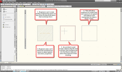
Xref Space Issues in AutoCAD MEP 2009

Back in ABS 2007, and ADT 2007, there was a new feature that combined the architectural spaces and the engineering spaces into one space object that could be shared between both deciplines.


Click on picture to see the problem.

Asking the Architect to move their spaces into a separate xref file, rather than placing spaces in the architectual model itself might be a lot to ask but it will be the only way that engineers will be able to use spaces and zones in their engineering models. The architect can start a new file that will be just for the Architectural spaces. The Architect would xref their background into this new file containing their spaces.

With their spaces off to the side, this should free up their backgrounds to allow engineers to make your own spaces.

In the meantime, Autodesk has logged a wish request to make Rooms different from Spaces so the engineer can model the volumes we need for calculations. Architects can model their Rooms. Kind of going back to what they had in 2007, and what Revit MEP 2009 has.