Sunday, October 29, 2006

Manually Migrating custom settings in ABS 2007

The Migrate Custom Settings tool is not included in Building Systems 2007. Autodesk has created this document to manually move files from your 2006 installation to your 2007 installation. The files that are migrated with the Migrate Custom Settings dialog box are listed below, along with a description of each file and other file details. You can use this information to help you decide whether you want to migrate a file.


*.arg

This file is used to back up user profile information from the system registry. The .arg file is not migrated. The changes you make to your user profile are stored in the system registry and are migrated.

An .arg file can be exported from the Profiles tab in the ACAD options dialog box. You can export the .arg file from ABS 2006 and either import the file into 2007 or set the shortcut path of ABS 2007 to point to the file during startup.

*.lin, acad.lin, acadiso.lin

These files are used to store your user-defined linetypes. Acad.lin contains standard linetype definitions (an AutoCAD library file). Acadiso.lin contains metric linetype definitions (an AutoCAD library file).

By default, the *.lin, acad.lin, and acadiso.lin files are found in the following location:

C:\Documents and Settings\[current user]\Application Data\Autodesk\ABS 2006\enu\Support

To migrate these settings into ABS 2007, move the files to the following location:

C:\Documents and Settings\[current user]\Application Data\Autodesk\ABS 2007\enu\Support

*.pat, acad.pat, acadiso.pat

These files are used to store your user-defined hatch patterns. Acad.pat contains standard hatch pattern definitions (an AutoCAD library file). Acadiso.pat contains metric hatch pattern definitions (an AutoCAD library file).

By default, the *.pat, acad.pat, acadiso.pat files are found in the following location:

C:\Documents and Settings\[current user]\Application Data\Autodesk\ABS 2006\enu\Support\pats

To migrate these settings into ABS 2007, move these files to the following location:

C:\Documents and Settings\[current user]\Application Data\Autodesk\ABS 2007\enu\Support\pats

Acad.pgp

This file is used to store shell commands and command alias definitions (a program parameters file in ASCII text form).

By default, the acad.pgp file is found in the following location:

C:\Documents and Settings\[current user]\Application Data\Autodesk\ABS 2006\enu\Support

To migrate these settings into ABS 2007, move the file to the following location:

C:\Documents and Settings\[current user]\Application Data\Autodesk\ABS 2007\enu\Support

*.mnu and *.mns

These files contain menu customizations from an AutoCAD® version prior to AutoCAD 2006.

These files can be loaded as partial CUI files using the CUI interface. Once these files are loaded into the main CUI, all the functions of these menus will be available.

*.cui

These files contain customizations from AutoCAD 2006 and newer versions.

By default, .cui files are found in the following location:

C:\Documents and Settings\[current user]\Application Data\Autodesk\ABS 2006\enu\Support

To bring these settings into ABS 2007, you can move the files to the following location:

C:\Documents and Settings\[current user]\Application Data\Autodesk\ABS 2005\enu\Support

It is strongly recommended that you create a workspace in ABS 2006, and then transfer the workspace into the ABS 2007 CUI using the Transfer tab in the CUI editor.

See this document on Autodesk's Website by clicking the link below.

Migrating custom settings in Architectural Desktop 2007


Monday, October 23, 2006

3rd Party BIM Estimating Tools

Innovaya Composer for ADT/ABS is an add-on program for Autodesk Architectural Desktop (ADT) and Autodesk Building Systems (ABS). By taking your multiple design files into a single model, Innovaya Composer for ADT and ABS help your project teams in communication, coordination, and automating and enhancing the process of quantity takeoff, cost estimating and scheduling by the use of it's many products. It imports ADT and ABS design element information into Innovaya project model and exports the model into an .INV file, which can be read by all Innovaya visual applications for visualization, communication, quantity takeoff, cost estimating, construction simulating, and so on.


With the .INV file, you can use one to four of Innovya’s software solutions.

Visual BIM

Innovaya Visual BIM provides intuitive and interactive user interfaces that allow users to browse detailed object information in an Autodesk Architectural Desktop® (ADT) or Autodesk Revit® model.

Visual Simulation

Innovaya Visual Simulation associates Building Information Models (BIM) objects with scheduling activities, performing 4D construction planning and constructability analysis.

Visual Quantification

Innovaya Visual Quantification performs object quantity takeoff accurately, quickly, and intelligently from Autodesk’s ADT/Revit.

Visual Estimating

Innovaya Visual Estimating performs cost estimating accurately, quickly, and intelligently by delivering objects from Autodesk’s ADT/Revit to Sage Timberline.

To request further product information or a product brochure, you can see their website here.

Innovaya Software Products


There is a great article about the details of how the Innovaya software works here at AEC Bytes.

Visual Estimating: Extending BIM to Construction

Friday, October 20, 2006

Migration of Legacy Building Systems Drawings Into 2007


Opening a drawing from a prior version of Building Systems into Building Systems 2007 may cause some features to behave unexpectedly. Below is a list of styles that will need to be inserted into your previous versions of Building Systems drawings in order to receive the full benefit of feature enhancements.
  • Electrical System Definitions
  • Cable Tray Rise Drop Styles
  • Conduit Rise Drop Styles
  • HVAC System Definitions
  • HVAC Rise Drop Styles
  • Pipe Part Routing Preference Definitions
  • Piping Systems Definitions
  • Pipe Rise Drop Styles
  • Plumbing Rise Drop Styles
  • Plumbing System Definitions
  • Schematic Pipe Styles
  • Schematic System Definitions
  • Display Configurations
  • Layer Key Styles

There are probably several methods to import this information into your existing drawing.

One method would be to start a new drawing using the 2007 ABS Model (Imperial Ctb).dwt and insert the legacy drawing as a block into this template, and explode it once. The 2007 template will have the additional styles, displays and layer keys needed for the legacy drawing to function.

Below is a second such method.

Styles:

  1. Open one of your existing drawings from a previous version of Building Systems
  2. From the Format menu, choose Style Manager
  3. From the File Menu in Style Manager, choose Open Drawing…
  4. Within the Open drawing dialog, Select the Content button in the left pane and then open the Template folder
  5. Set the Files of type: field to Drawing Template (*.dwt)
  6. Open the ABS Model (Imperial Ctb).dwt. Now you may pick and choose the desired styles to update in your existing drawing
  7. Within the left pane of Style Manager expand ABS Model (Imperial Ctb).dwt
  8. Select the Electrical Objects folder and drag to your current drawing listing
  9. The Import/Export – Duplicate Names Found dialog is displayed Select the desired Merge Style method (for most cases use Overwrite Existing) and choose OK.
    By choosing the entire Electrical folder all Styles found within the folder will adhere to the Merge Style specified. If you wish, expanding the folder will allow further control over individual types of files and even individual styles.
  10. Repeat steps 8 and 9 for the Documentation Objects, HVAC Objects, Piping Objects, Plumbing Objects and Schematic Objects as desired
  11. Choose Apply and OK to close Style Manager with the changes

Displays:

  1. From the Format Menu, choose Display Manager
  2. From the File Menu in Display Manager, choose Open Drawing
  3. Within the Open drawing dialog, Select the Content button in the left pane and then open the Template folder
  4. Set the Files of type: field to Drawing Template (*.dwt)
  5. Open the ABS Model (Imperial Ctb).dwt
  6. Within the left pane of Display Manager expand ABS Model (Imperial Ctb).dwt
  7. Select the Representation by Objects folder and drag to your current drawing listing
  8. The Import/Export – Duplicate Names Found dialog is displayed. Select the desired Merge Style method (for most cases use Overwrite Existing ) and choose OK
  9. Repeat steps 7 and 8 for Sets and then Configurations
  10. Choose Apply and OK to close Display Manager with the changes

Layer Keys:

  1. From the Format menu, choose Layer Management> Select Layer Standard
  2. On the Layering tab, set the Layer Key Style to ABS Objects – AIA 256 Color
  3. Choose OK

For best results, it is recommended that previous version drawings are opened and saved in 2007 format before attempting to combine them, through Block Insert or Xref, with 2007 format drawings.

Opening drawings from previous version of Building Systems which contain eSpaces, the eSpace(s) will be migrated to Space object(s). During the migration process the displays from eSpaces and Spaces will be combined. The resulting Spaces in Building Systems 2007 may have two hatches applied instead of only one for the previous version of Building Systems. The multiple hatches are due to the combining of the displays. In earlier version of Building Systems the Spaces use the hatch component on the Plan Screened display representation and eSpaces used the hatch component from the Plan display representation. To correct this behavior in Building Systems 2007 perform the following:

  1. From the Format menu, choose Display Manager
  2. Expand the Representation by Objects section
  3. Select Space within the tree view pane.
  4. Within the right pane uncheck the Plan Screened display representation for the Display Set in bold and/or any other desired display set.
  5. Choose Apply and OK.

In Building Systems 2007, duct connectors have been changed to support multiple connection types. With this change, the Duct catalogs have been collapsed to remove redundant parts that are found in each connection type. When a drawing from a previous version of Building Systems is opened and a duct part is modified, the selected part is mapped to a part in the restructured duct catalog. If a user created part from a previous version of Building Systems is being modified and the part does not exist in the current catalog, the user is prompted with: “The selected part(s) do not exist in the current catalog. Do you want to continue modifying the part(s)?” If YES is chosen, the user will need to select a new part from the currently loaded catalog prior to making any further modifications.

When previous version drawings are opened, a dialog is displayed with a warning that saving this drawing will upgrade AEC objects to 2007 format. If a previous version drawing is opened by double-clicking the file in Windows Explorer, this dialog may be hidden behind the drawing making Building Systems appear to have hung; clicking anywhere on the application to give it focus will make the dialog come to the foreground.

Monday, October 16, 2006

Google Sketchup ADT Plugin


Scott's House
Google SketchUp (free) is an easy-to-learn 3D modeling program whose few simple tools enable you to create 3D models of houses, sheds, decks, home additions. You can add details, textures and glass to your models, and place your finished models in Google Earth, share them with others by posting them to the 3D Warehouse, or print hard copies. With no training, and my first sketch, I was able to draw my house in just a couple hours.

The ease of use and flexibility of modeling in SketchUp provides a powerful alternative to using ADT Mass Elements. Now you can bring SketchUp model geometry directly into ADT/ABS in two ways:
  • As straight up geometry - all vertical surfaces become walls, all horizontal surfaces become slabs and sloping surfaces become roof elements.
  • As translated geometry based on material or layer.


    Autodesk Architectural Desktop Plugin

Autodesk Building Systems 2007 Service Pack 1

Summary of the Primary Building Systems Issues Resolved by the Service Pack

As a result of detailed information from customers who used the Customer Error Reporting Utility, a number of stability improvements have been made in the following feature areas:

Content Builder

  • In Building Systems 2007 we require all content that contains pipe connectors to have a CEL (Connector Engagement Length) value specified on each pipe connector.� CEL parameter is now added or removed automatically when a new pipe connector is added to or removed from a piece of content.

Duct

  • When transitioning from a rectangular to round duct segment the default duct fitting will be the same as transitioning from a round to rectangular duct segment.� You will no longer receive the "No Default Part Set" dialog during this action.
  • Insulation and Lining will be displayed on radius elbows.

Export to AutoCAD

  • Due to XDATA on hatches within our content, Export to AutoCAD silently failed to create exported drawing file in Building Systems 2007.� This scenario with Export to AutoCAD has been resolved.

Labels

  • Deleting an auto-placed label on a pipe segment will no longer leave a gap in the pipe segment display where the label previously was.

Property Palette

  • Location values on all layout objects have been added back to the Property Palette when the segment(s) are selected.

System

  • Gaps on Schematic Lines, Schematic Pipes and Wires are now retained through External References.

Callouts

  • "Style not found in location drawing. Using Standard style." message no longer displays at command line when adding callouts to View drawings.

Export to AutoCAD

  • "An error occurred during save." message is no longer displayed after use of the Export to AutoCAD command.

Interferences

  • Interferences are now handled correctly through nested external references.

Object Display Dialog

  • The Object Display dialog no longer becomes unresponsive after accessing and dismissing the Material Definition Properties dialog.

Performance

  • Performance improvements when zooming in and out while in an isometric view.

Project Management

  • Performance improvements when working with project drawings across a network or WAN.
  • "Enhanced reference audit problems for database" messages no longer display at the command line when dragging and dropping View drawings into Sheet drawings.
  • View drawings can be dragged and dropped into Sheet drawings within projects upgraded from previous releases.
  • When publishing sheets, newly created page setups are now displayed in the list associated with the Publish using Page Setup Override flyout.

Schedule Tables

  • Images included in schedule tables through use of graphic property definitions are now incorporated in 2D and 3D DWF files.

Schedule Tags

  • Assigned units within Property Data Formats are now reflected in schedule tags.
  • When drawings are opened, the correct value for AreaMinusInterferences property sets is displayed in schedule tags.

Spaces

  • The Cancel button in the Analyzing Potential Spaces dialog is now functional.
  • Space/Zone Manager updates correctly after adding openings to a space that is displayed multiple times in the Space/Zone Manager tree.
  • Within the Space/Zone Manager, the style associated with the ceiling and floor surfaces can now be edited for associative extrusion spaces.
  • WallArea property set definition now reports correct value for sloping surfaces on freeform spaces.
  • Enabling the Ignore holes option in the Generate Spaces dialog now affects the results of Space AutoGenerate command.
  • The diagnostic display of spaces is no longer affected by the Offset Boundaries setting.
  • The diagnostic display of spaces is now updated correctly after the space geometry has been updated when using ByStyle as offset boundaries type.
  • Objects that reside on frozen layers within external references are now ignored when spaces are generated.
  • "Enhanced reference audit problems for database" messages no longer display at the command line and improved performance when opening drawings in which spaces have been generated from walls.
  • Openings associated with floor and ceiling surfaces are now correctly displayed after changing the Height below floor value.
  • Spaces are no longer generated inside the door/window swing when doors or windows are anchored to a wall.
  • Volume above ceiling values no longer vary depending on the geometry type of spaces.
  • When generating spaces, AEC Polygons, Stairs and Railings are now accepted as linework.
  • The Audit command has been enhanced to allow the identification and fixing of errors related to spaces.
  • Roofs, roof slabs and slabs will not participate as bounding objects when generating an extrusion or 2D space.

Tool Palettes

  • Manually created project palette groups are no longer lost after the project is closed and re-opened.

Zones

  • The Properties Palette displays the correct dimension values for spaces that are associated with nested zones.
  • After the zone match option is used, newly created spaces are no longer automatically added to zones.
  • Inserting a zone template into a drawing with an existing space does no longer results in an inaccurate zone template.

3D Navigation

  • Intellimouse scrolling with ZOOMWHEEL set to 1 now works as expected when in Orbit mode.
  • 3DORBIT performance has been improved.

External References

  • Constant reload of relative external references has been resolved.
  • IMAGEATTACH of CMYK images no longer result in Invalid Image warnings.
  • DWF files produced with Revit Structure 2 or 3 can now be attached to AutoCAD drawings.

Autodesk Building Systems 2007 Service Pack 1

ABS Based on Applicable Building Codes and Equipment Specs


An important Whitepaper written by Autodesk describing how AutoCAD MEP meets industry standards in its program.

Download Whitepaper Here

Introduction
Engineering designs must meet strict guidelines and codes to ensure that structures are safe and economical for the public and to maintain design consistency throughout the industry. AutoCAD MEP software enables engineers to create an object-based systems model that follows industry standards. Whether you’re using the duct sizing tool, placing a piece of electrical equipment, or sizing a sanitary main, AutoCAD MEP helps ensure that your data is based on applicable codes and guidelines or on equipment specifications from leading manufacturers. This white paper shows how the codes, guidelines, and equipment specifications built in to MEP software can help you improve accuracy and ensure that your designs meet industry standards.

HVAC Ductwork and Piping
Take a look at the guidelines that influence the development of ductwork and piping design tools within AutoCAD MEP and compare them with the way you design today. Feeling confident with your engineering design is what it’s all about.

Duct Sizing Calculator
Designers who have sized ductwork are probably familiar with the Trane Ductulator tool—that handy little cardboard square with the rotating circle in the middle. In fact, most engineers have customized the tool by marking the design criteria they use most often. Engineers rely on this duct-sizing tool because it is based on equations derived from the industry-benchmark ASHRAE (American Society of Heating, Refrigerating, and Air- Conditioning Engineers) standard.

The AutoCAD MEP duct sizing tool is derived from the same standard, ASHRAE Fundamentals Handbook 1997, and can be found in the Add Duct dialog box. From this dialog box you can select the system type (supply, return, exhaust, and so forth), enter the airflow (CFM), and choose the Calculate button. If you are routing round ductwork, calculate the diameter. If your design calls for oval or rectangular ducts, calculate either the width or the height. And as with any MEP tool, if you’re not satisfied with the calculated result, you can simply select a different size.

The design criteria you specify for duct sizing is linked to the system type chosen. To specify that criteria, choose the HVAC System Definition. Select a system type, and then select the Design Parameters tab. Here you can decide whether to size your ducts for this system based on air velocity or static pressure drop per 100 feet of duct. You can also determine a roughness coefficient as well as air density. Being able to specify these parameters per system type is helpful. For example, you can create a low-pressure supply duct system and a medium-pressure supply duct system and use different sizing parameters for each. This is just like marking your Ductulator at .08 inch per 100 feet for low-pressure ducts and at 0.3 inch per 100 feet for medium-pressure ducts.

HVAC Load Calculations and Duct Sizing
One of the first tasks assigned to new HVAC designers is running a load on a building. Performing this task gives engineers-in-training their first look at what goes into a building load calculation and how those components affect their design, such as building construction, people densities, outdoor air requirements, equipment loads, lighting loads, building zones to optimize equipment loading, building orientation, and much more. Manually transferring this data to load calculation software can be tedious and prone to errors.

AutoCAD MEP helps eliminate costly errors by enabling designers to transfer data from the building model directly to engineering analysis applications like Trane’s Trace 700, IES, Varitrane Duct Designer, or Elite Ductsize. Use standard file formats, such as gbXML and ddXML, to directly import building design data. Once the design data has been transferred, use Trace 700 to perform heating and cooling load analyses, and Varitrane Duct Designer and Elite Ductsize to calculate optimal duct sizes using the static regain, equal friction, or constant velocity method.

HVAC Equipment—MvParts
Equipment location is an integral part of any HVAC design. Coordinating space requirements, function, and ease of maintenance for each piece of equipment is essential for its placement. Equally important is ensuring that systems don’t conflict with other equipment or structural components in the design.

AutoCAD MEP provides an extensive catalog of equipment made up of MvParts. Each piece of equipment has intelligent connection points for fast and easy connections to ductwork, piping, electrical conduit, and more. MvPart objects also have the ability to check for interferences with other components in your design, making it easier to coordinate your mechanical rooms, electrical rooms, chases, and above-ceiling space.

The nonproprietary equipment specifications provided in AutoCAD MEP are based on equipment offerings from leading manufacturers. Dimensions and connection sizes are matched against several different manufacturers, and the most relevant data is used. For example, Trane and Carrier both offer packaged rooftop air conditioning units. The dimensions for length, width, and height of the equipment casings are similar for comparable tonnages but not exactly the same. For similar units such as these, Building Systems uses the largest dimensions.

Ducts and Fittings
Most HVAC engineers have had to either write or edit a ductwork and fittings specification that references ASHRAE and SMACNA. AutoCAD MEP ductwork and fittings are based on the ASHRAE Duct Fitting Database (1994), the Round, Rectangular, and Oval Duct Industrial Construction Standards published by SMACNA, and are augmented by offerings from the leading manufacturer of duct and duct fittings in the United States (and primary author of aforementioned standards).

Pipe and Fittings
Traditional methods of creating double-line HVAC piping drawings are time consuming and inaccurate. Using standard CAD tools, engineers offset simple lines to nominal pipe sizes and frequently use a box or bowtie symbol to represent various valves and appurtenances. Nominal pipe sizes, loosely related to the actual pipe dimensions, are used for convenience, with elementary symbols representing more complex objects, such as valves and gauges, to save time. Often these symbols are not drawn to the actual sizes of the piping components they represent and can result in costly change orders in the field.

AutoCAD MEP can help reduce drawing inaccuracies and coordination issues because all pipes and pipe fittings are based on widely recognized standards, codes, and offerings from leading manufacturers. Pipe identification, outer dimensions, and nominal dimensions are referenced against ANSIB36.19, and ANSI B36.19 as published in Crane’s Technical Paper No. 410. For example, using Building Systems, draw a piece of 6-inch diameter, schedule 40, carbon steel pipe with flanged connections (apply Building Systems Floor – 2 Line Display). Now check the outer dimension of the pipe. Even though you drew a 6-inch nominal size diameter pipe, you get the actual ANSI-specified outer dimension (6 5/8 inch) for that particular type of pipe, resulting in a more accurate design.

Pipe fittings are referenced against various applicable standards:
● Flange: ANSI/ASME B16.5
● Socket Weld and Threaded: ANSI/ASME B16.11
● Cast Iron: ANSI/ASME B16.12 and 16.13
● Butt Welded: ANSI/ASME B16.9
● Grooved: Not described in standard, based on offering from leading manufacturer
● Brazed: ANSI/ASME B16.18, B16.22, B16.23, and B16.29 among others
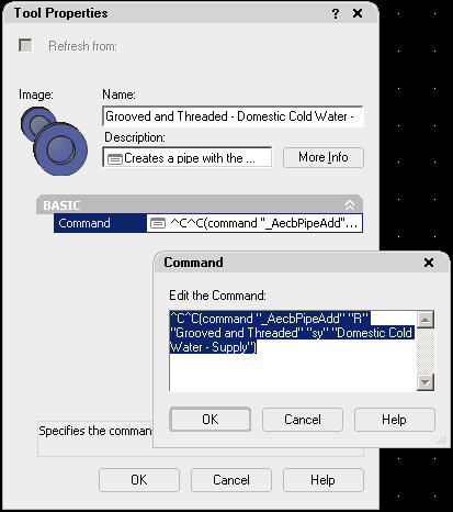
Plumbing
Plumbing design relies heavily on code requirements for sizing domestic water, sanitary sewer and ventilation pipes. Why not use an application that can incorporate the code requirements your company follows directly into its design tools.

Plumbing Fixtures—MvParts
Traditionally, architects have located the plumbing fixtures in their designs. Now that the connectivity of AutoCAD MEP objects can span the xref barrier, plumbing engineers and designers can place toilets, urinals, sinks, and more in architectural drawings. For effective use, these fixtures must be based on leading manufacturers’ offerings so that dimensions and sizes can be trusted. That’s exactly what Autodesk
Building Systems does. Whether you’re placing a floor drain, drinking fountain, toilet, or lavatory, Building Systems helps to ensure that the plumbing fixtures in your designs match industry standards.

Plumbing Pipe Sizing
In the past, sizing plumbing piping required thumbing through page after page of code. AutoCAD MEP alleviates the tedium by providing sizing tools for supply water piping and sanitary piping based on the Uniform Plumbing Code–2000, Crane’s Technical Paper No. 410, American Society of Plumbing Engineers (ASPE) chapter interpretations, and engineering judgment.

A typical method for sizing water piping is to tally the load values based on a fixture count, convert that fixture unit count to gallons per minute (GPM) requirement, and use a diagram that illustrates the relationship between GPM, pressure drop per 100 feet, and fluid velocity. Assuming the pressure loss through taps, tees, valves, and other appurtenances has been accounted for and compared to available water pressure, a pipe size can be obtained from the diagram. However, performing this process manually can be tedious and time consuming.

AutoCAD MEP simplifies this process by providing a load demand table based on Uniform Plumbing Code 2000. You can easily edit this table or create a new one to meet your company’s requirements. With the fixtures in place and the water piping connected, you can then use the supply pipe sizing calculator. Use the Size Supply Pipe dialog box to modify different factors affecting pipe sizing, such as fluid velocity (feet per second), available pressure (psi), and pressure at highest fixture (psi). It also includes a customizable pipe sizing table that provides equivalent length data for various fittings. Other data fields in the dialog box are populated when you have selected a pipe segment to size. The software calculates a pipe size using the Hazen-Williams friction loss formula and a derivation of the Hunter’s Curve referenced from ASPE.

AutoCAD MEP also provides a sanitary pipe sizing calculator, which extracts the fixture units connected to the pipe segment being sized and compares this value to maximum permissible load data stored in the sanitary pipe sizing table. The load data is further categorized as stacks, branches, or offsets to accommodate different design conditions. The sanitary pipe sizing table, like the fixture unit table, is based on Uniform Plumbing Code 2000. Customize this table or create a new one to reflect the codes and standards your company follows.

Fire Protection
AutoCAD MEP fire protection content was created using industry standards. Customize your fire protection designs by taking advantage on “in-the-box” content design tools to create more equipment on the fly.

Fire Protection—MvParts
Like other engineering equipment included in AutoCAD MEP, the equipment provided for fire protection is based on specifications from leading manufacturers. Equipment includes wet and dry sprinklers, various types of hose cabinets, fire department connections, hose connections, applicable valves, and tanks. Fire protection equipment is included with Mechanical MvParts.

Fire Protection Pipe and Fittings
With AutoCAD MEP, add fire protection pipe and fittings to your design using the Add Pipe command for HVAC piping. Since both disciplines use virtually the same types of pipes and fittings, the standards and guidelines referenced in the HVAC Pipe and Fittings section apply here as well.

Electrical
Electrical designs require code compliance. Use Building Systems electrical design tools with confidence knowing that your construction documents meet the requirements set forth by code officials and local authorities.

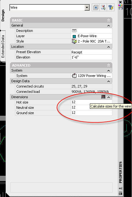
Electrical Wire Sizing
Looking up wire sizes manually in the National Electric Code ampacity tables is a tedious and time-consuming job. AutoCAD MEP automates that process. To use wire sizing, you first draw the wiring, associate it with a circuit, and designate a wire style. If no wire style is specified for the circuit, the wire cannot be sized. The circuit must be assigned because the conductors are sized based on the circuit rating. With the necessary values in place, Building Systems retrieves wire sizes from the ampacity table in the wire database (ampacity.mdb). This table is arranged in much the same way as the National Electric Code table 310-16. It includes columns for ground conductor sizing for both copper and aluminum conductors, similar to the table in section 250-122 of the National Electric Code. An additional table (ambients.mdb) contains correction factors ased on ambient temperatures specified in National Electric Code 310-16. These tables rovide the information required for accurate wire sizing and are fully customizable using icrosoft® Access.
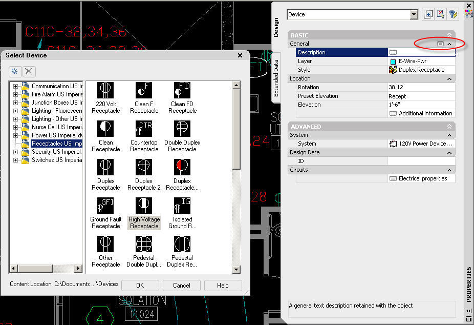
Electrical—MvParts
AutoCAD MEP includes a wide selection of electrical equipment based on specifications from leading manufacturers. The electrical MvParts catalog includes equipment such as transfer switches, motor starters, termination boxes, variable frequency drives, and emergency power generators. Providing intelligent connections and enhanced properties, electrical MvParts can be easily integrated into your designs. If you’re accustomed to specifying equipment from a manufacturer that is not included in Building Systems, you can create that content using the Content Builder—a feature that has come a long way since earlier releases. In just a few steps, you can create large catalogs of equipment quickly and easily. Before creating custom content, however, check out the manufacturer’s website to see if they offer the equipment you need. Many manufacturers have already created MvPart catalogs of their equipment, which you can drag into your design using i-drop® technology.
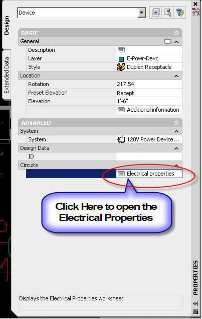
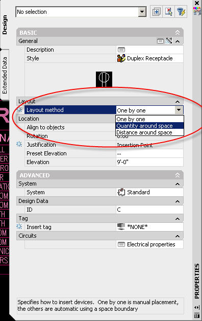
Electrical Devices
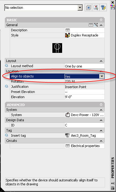
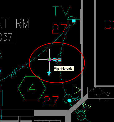
Electrical devices are the primary graphical objects used in electrical drawings. Generally schematic in nature, they can contain additional 3D blocks as part of the object, which makes them useful for interior elevations and interference detection with other building systems objects such as ductwork and piping. The connectors for electrical devices are different from the connectors for MvParts and are created using the Style Manager. Electrical devices modeled as symbols have been developed using the same standards as symbols. And if they contain 3D elements, they are referenced against data from leading manufacturers.
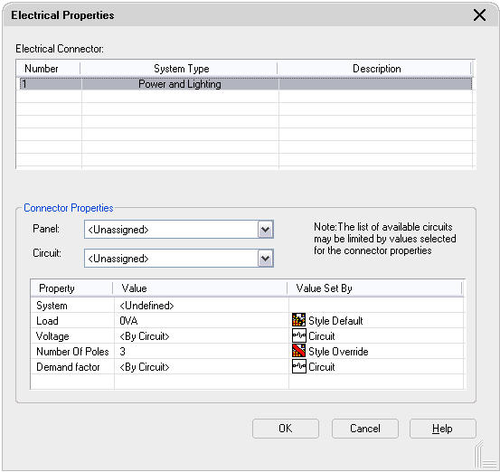
Electrical Panels
Electrical panels are similar to electrical devices but do not have connectors. They are an integral part of electrical designs created with AutoCAD MEP because circuits cannot be created without them. Although you can draw the wiring, the circuit it represents will not exist. The panels that ship with AutoCAD MEP are model-based parts that are referenced against offerings from leading manufacturers where appropriate, but are mostly generic. You can easily create new panel types through the Style Manager to meet the specifications of the manufacturer you choose.

Electrical Conduit and Cable Tray
The 3D components of conduit and cable tray are useful when coordinating clearances above ceilings, determining space constraints in electrical equipment rooms, and checking interferences with ductwork and piping. The most commonly used standards are NEMA FB 1 for conduit and NEMA VE1 – 1998 for cable tray. AutoCAD MEP uses these standards for conduit and cable tray content.

Symbology
Companies doing engineering design work need to establish drafting standards. AutoCAD MEP incorporates the most common standards and guidelines used in the industry. Many of the original symbols used in AutoCAD MEP software came from Softdesk® 8, which were referenced to various AMSI and ISO guidelines. In addition, symbols included many user requests for specific images that may or may not have met various code requirements. These symbols were matched against the ASHRAE Fundamentals Handbook, Chapter 34, Abbreviations and Symbols, the AIA Architectural Graphical Standards, and the SMACNA CAD Standard. However, not all symbols have a match in these standards. All new symbols added to AutoCAD MEP meet specific applicable codes such as NFPA 170 – 2002.

Connector symbology for single-line piping such as grooved, welded, threaded, bell and spigot, brazed, flanged, glued, and socket welded were referenced against the National CAD Standard and ASHRAE Fundamentals Handbook. A few of these connectors were not described in either of these standards, so graphics were based on alternate resources such as data from leading manufacturers.

Template Content and Styles
Establishing template content and styles based on your current design practices sets you on the path of increased productivity. Once your standards have been incorporated into the software, you’ll find that creating model-based designs doesn’t get any easier.

Templates
Template content and styles in AutoCAD MEP cover everything from duct and pipe system types to electrical voltage definitions. You can customize templates to meet your company’s requirements or get started quickly out of the box with the default templates that ship with the software. For example, without using one of the electrical templates the values that are stored for electrical preferences would not exist. Voltage definitions would be undefined, requiring you to create them manually. Without specifying voltage definitions, you could not add circuits to the drawing. The template content comes from a variety of sources, including but not limited to the Uniform Plumbing Code, the National CAD Standard, the SMACNA CAD Standard, ASHRAE Fundamentals Handbook 1997, National Electric Code, ASPE Data Books, engineering judgment, and, most important, the AIA Architectural Graphic Standards.

System Definitions
Various system definitions are provided in the templates for each of the disciplines: HVAC, plumbing, and electrical. Based on different reference materials and guidelines, engineering judgment was used to determine the different system types available out of the box. The important thing to note about system definitions is that you’re not limited to the examples provided in AutoCAD MEP. These system definitions were offered to help you start designing quickly and to serve as examples of how to create other system types. Once you’re familiar with Building Systems software, you can create and customize system types as needed.

Labeling Standards
Labeling engineering designs manually is a tedious and time-consuming task. AutoCAD MEP automates much of the annotation. From labeling a rectangular duct size to automatically tagging an electrical device upon insertion, your productivity increases and your design accuracy improves. Because labeling is not standardized across the industry, many of the labeling styles are based on engineering judgment. And like most Building Systems design tools, annotation is highly customizable so you can meet your company’s unique needs.

Conclusion
AutoCAD MEP is easy-to-use design software that increases productivity, enhances collaboration among design team members, and improves workflow efficiencies using an object-based systems model. Building Systems improves on existing methods for creating construction documentation while supporting traditional design requirements. The most widely accepted engineering codes, standards, and guidelines have been incorporated into AutoCAD MEP to help ensure that your designs meet industry standards. Furthermore, all tables, symbology, system settings, and values can be customized as necessary to meet the requirements of your organization, while still meeting industry requirements.

Improve workstation performance when running Autodesk Building Systems

Discover tips and techniques from Autodesk that can improve workstation performance when running Autodesk Building Systems. This paper explores methods of maximizing workstation performance when using your CAD application on large projects.

For Project Managers and CAD Managers

The following tips and techniques are for project managers and CAD managers responsible for rolling out software releases, establishing requirements, managing projects, supporting CAD users, and so forth.


Work in the Latest Release

Each new release of Autodesk Building Systems is designed to handle larger and morecomplex projects. Each new release contains significant advances in performance as well as new features and enhancements that further streamline work processes. These improvements enable you to work faster and reduce the time it takes to perform complex tasks.

Standardize on Drawing Format

Over the course of a project, team members use different versions of AutoCAD®, Autodesk® Architectural Desktop, or Autodesk Building Systems software to create data, especially if the project uses drawings from a client or subcontractor. However, these drawings are converted to current file format on the fly every time they are opened or referenced through an external reference file (xref). Opening and saving earlier-version project drawings in the current release eliminates this time-consuming conversion, thus freeing resources and shortening the time to open the drawings.

Manage Proxies

Drawings may contain proxies of custom objects created in other AutoCAD-based applications or third-party software. These objects require that proxy graphics be turned on in these drawings, which can significantly increase file sizes and the amount of time required to open those files. For example, a 3.9 MB drawing seen recently in Autodesk Product Support was reduced to 1.8 MB just by turning proxy graphics off.

Avoid Complex MvParts

When developing content for your catalog, carefully consider the complexity of each new part. For example, the round louvered diffuser shown below is much too detailed for most MEP work. It uses curved surfaces for interior vanes, shows all the ribbing between the vanes, and has a neck with an internal curved surface that’s hidden when connected to your ductwork system. This depth of complexity taxes the resources of your workstation for little gain, requiring a high level of system resources every time you need to change views.

Tip: Use MvParts that convey the basic intent of what the equipment represents, and avoid making MvParts more detailed than they need to be.

Use Project Navigator Effectively

When using Project Navigator, do not manually insert xrefs into your drawing using the Reference command on the Insert menu. Instead, use the shortcut menus in Project Navigator to attach or overlay reference files within the project.

In versions prior to Autodesk Building Systems 2005 (SP2), drawings that are manually referenced into a project are not resolved in the file structure created through Project Navigator. Accordingly, the referenced path of manually inserted xrefs may be lost when paths change, resulting in missing or incorrect reference files.

Tip: Overlay xrefs rather than attaching them. Drawing files that use xref overlay will not reproduce that overlay when it is referenced by another drawing. Drawings with attached xrefs will reproduce that xref, which can lead to duplicate or circular xrefs and confusion as to what actually is in the drawing. This can tax workstation resources and affect performance. For example, a data set recently received by Autodesk Product Support contained drawings with attached xrefs that resulted in nine duplicated referenced drawings.

Avoid Hidden Shares

Earlier versions of Autodesk Building Systems (pre-2006) support only a full UNC path with no mapped drives and no relative paths. Best practices suggest avoiding a project structure that points to hidden shares, especially if the project structure is sent to other members of the extended design team that might not have those same shares.

Manage Temporary Files

Temporary files are created as part of the “Enabled with Copy” demand load strategy built into Project Navigator. These files remain after a system failure or an aborted Project Navigator activity. Deleting the *.ac$ files in the Temp folder can reduce the time required to open most drawing files and significantly improve system performance.

Tip: Update the Autodesk Building Systems profile to point all AutoCAD temporary files to a specific temporary folder separate from the standard Microsoft® Windows® temporary folder. Use a login script to clear temporary files on a daily basis.

Hardware Recommendations

Turn off the system’s hardware acceleration, update all graphic drivers to their latest version, and make sure your workstation meets the minimum system requirements for the release you are using. Minimum system requirements can be found in the installer menu and the help files.

For CAD Users

The following tips and techniques are for the everyday CAD user responsible managing drawings, adhering to CAD standards, coordinating designs with the extended team, creating construction documents, and so forth.

Use Purge Commands

At the end of a work session, use the purge commands—PURGE and BLDSYSPURGE— to clean up Autodesk Building Systems drawings. For example, a 3.2 MB drawing recently came into Autodesk Product Support with complaints of poor system performance. Upon inspection, about two-thirds of the objects in the drawing were not being used (2,166 of 3,153 items). Purging reduced the drawing size to about 1.9 MB. Since Autodesk Building Systems always verifies the location of objects relative to new objects being added, purging can dramatically improve system performance.

Use Interference Detection

Turn interference detection on only when you need it. For example, wait until systems are substantially complete and ready to be compared to other nearby systems in the drawing. Autodesk Building Systems compares the location of each object to others in a drawing— an activity that uses a lot of system resources. Turning interference detection off when you don’t need it drastically reduces the time it takes to open any drawing.

Tip: When checking interferences on a color system scheme, create a new Layout tab and use the Page Setup manager to set all colors, other than the collision marker, to black. The result is a black-and-white screen with colored collision markers that are easy to identify.

Minimize Multiple Sessions

Launching multiple or concurrent sessions of Autodesk Building Systems, Autodesk Architectural Desktop, AutoCAD, or other similar third-party products built on AutoCAD software dramatically reduces system performance and possibly the system’s overall stability. Avoid this practice and adopt other work methods. If you cannot avoid multiple sessions, consider using your most capable workstations for these situations.

Let Processes Run Their Course

It is normal for some activities, such as loading xrefs, to take time. These processes need to run their course before additional activities can be initiated, such as dragging drawings from Project Navigator before it has finished loading previous drawings.

Minimize X-Clips and Live Sections

Live sections and x-clipping of xrefs are useful for working with the live model. However, too many x-clips and live sections can cause the drawing to load very slowly.

Use 2D Wireframe

With the high quality of Autodesk Building Systems models, it is tempting to create walkthrough models in shade mode. Although such walkthroughs are great for visualizing the systems and their environment, shade mode, including 3D wireframe, taxes your system resources.

Tip: In complicated areas such equipment rooms, select the objects you want to view or work with and use the Isolate Objects feature to remove the surroundings. Not only will you see your work more clearly, system performance will greatly increase.

Manage Haloed Lines

Haloed lines generate a lot of additional data. Improve the time-to-open performance of any drawing by ensuring that the Increase Drawing Open Performance option is selected in the Building Systems Crossed Object tab in the AutoCAD Options. However, be cautious when selecting this option because it significantly increases your drawing file size.

Tip: Make sure you are getting the best system performance possible with haloed lines by ensuring that the Increase Drawing Open Performance option is selected. However, if you need to email drawing files or save them over a slow network, deselect this option to decrease drawing file sizes.

Manage Duct Hatching

It’s normal practice to use duct hatch on systems marked for demolition. However, hatching increases memory use and slows down all display-related activities such as opening drawings, regenerating models, and switching views.

Getting The Most Out Of Autodesk Building Systems

Friday, October 06, 2006

ABS 2007.1 New Features

This Preview provides detailed information about 2007.1 features.

Electrical tools on the Property Palette:

Device, Panel and Wire objects have been moved to the Properties Palette. All add, modify and properties functions now occur through the Properties Palette.

  1. To modify the electrical connectors of devices, Select the devices. On the Properties palette, expand Advanced, expand Circuits, and click Electrical Properties.
  2. On the Electrical Properties worksheet, select a connector. Select a circuit to assign the selected connector on all of the devices to it.

  3. Select Unassigned to remove any circuit assignments from the devices.

Auto-Align Devices:

Device objects can auto-align to lines, arcs, circles, splines, polylines, walls, ceiling grids, and space boundaries.

Open the Power-Lighting Device tool palette, and select a receptacle tool.

  1. On the Properties palette, change the style of the receptacle to be added by expanding Basic, and on the General bar, click properties. In the left pane of the Select Device worksheet, navigate to the drawing that contains the style. In the right pane, select the style, and click OK.
  2. In the Properties palette, expand Layout, and for Layou t method, select either "One by One"
  3. Expand Location, and for Align to objects, select Yes. This causes the receptacle to align to the object to which you snap. You can snap and align to a wall, ceiling grid, space boundary, line, polyline, spline, arc, or circle in the current drawing or in a referenced drawing (xref).


Auto-Layout Devices to Space:

Device objects can be inserted along a Space Boundary either by Distance around Space or Quantity around Space

  1. On the Power-Lighting Device tool palette, select a receptacle tool.
  2. On the Properties palette, change the style of the receptacle to be added by expa nding Basic, and on the General bar , click properties. In the left pane of the Select Device worksheet, navigate to the drawing that contains the style. In the right pane, select the style, and click OK.
  3. Expand Layout, and for Layout method, select "Distance around space". For Distance between, enter a value. You can also enter a value by clicking and specifying 2 points in the drawing. In the drawing, move the cursor to the location for the first device. This must be a point on the space boundary.
  4. Examine the preview of the receptacle layout, and if necessary, move the cursor to a different location on the boundary.
  5. On the Properties palette, you can view the value for Number of devices. This read-only property is updated when the preview is displayed.
  6. Click to insert the receptacles, an d press Enter to end the command.

Improved Grips on Wires:

Grips on Wire objects have been improved to allow easier access to Wire mid-point grip and Tick Mark Location. In addition, a grip has been added to Flip the tick mark.

  1. Select the wires.
  2. On the Properties palette, expand Basic, and modify the basic properties as needed:


Spline Wire Segment:

Spline segment type has been added for Wires.


Manage Circuit Data through External References:

Electrical Project Database functionality has been expanded to allow Circuit Manager to detect loads on the entire project. Electrical Project Database notification is added to the Status bar and functions similar to the xref notification.

  • You can use an electrical project database drawing to manage circuits across all drawings in a project.
  • You can create circuits when you add a panel, or you can add circuits to panels later.
  • You can configure circuit settings only in the drawing that contains the circuits. After you assign at least one device to a circuit, you cannot edit many of the circuit settings.
  • You can assign devices to circuits as you add the devices, or you can add the devices first and then assign them to circuits later.
  • You can keep circuit data current in multiple electrical drawings by reloading the project database.
  • You can configure electrical preferences so that you are automatically notified of circuit overloads for power and lighting circuits.
  • You can use circuit-checking features to see circuit information for a selected device. You can also check circuit connectivity to display which devices are assigned to the same circuit.
  • As you refine your designs, you can move circuits around on a panel to balance loads. You can also drag and drop circuits from one panel to another.
  • You can generate panel schedules automatically from the circuit data.

Electrical – Device Style and Panel Style Reorganization:

Device and Panel styles are reorganized and categorized to better suit the electrical design workflow.


Schematic – Electrical Schematic Symbol Style Reorganization:

Electrical based Schematic Symbol styles are reorganized and categorized to better suit the electrical design workflow.


Wire Size Calculator on Property Palette:

Electrical wire calculations are done by selecting the wire, and going to the properties palette, and click on
"calculate wire size" button.


Modify Your Tool Palette to Match Custom System Definitions and More


If you have created your own ABS System Definitions in the style manager, you may want to access those systems more quickly by selecting a duct, pipe, conduit, wire, cable tray, etc by a system, rather than selecting the system after opening the Add Duct dialog box. You can modify your Tool Palette for any workspace by right-clicking on the tool and go to the properties. Once you are in the properties, you can change the name from the ABS system to your system name. Then click on the Command, which will allow you to edit the command. The macro you will see in there will look like this.

^C^C(command "_AecbDuctAdd" "SY" "Outdoor Air")

Change the "Outdoor Air" to "Your Custom System Definition Name" . You can do the same for pipe and conduit and cable tray. Not only can you specify the system definition in the command edit box, but also the pipe routing preference as well. You can do this by adding "R" and the name of your routing preference.

^C^C(command "_AecbPipeAdd" "R" "Grooved and Threaded" "sy" "Domestic Cold Water - Supply")

If you want to your pipe tool to automatically specify a specific pipe size, add "si" and the size to the command edit box.

^C^C(command "_AecbPipeAdd" "R" "Standard" "si" "2")
Electrical Panels have additional variables to specify a specific Panel Style and the number of slots in the command edit box. "st" will pick a panel style, and "sl" will pick the number of slots your panel will have.

^C^C(command "_AecbPanelAdd" "st" "Recessed 1 (12 Slots)" "sl" "12")
Devices have these shortcuts also to automatically go directly to the device category. Just use the "li" in the command editor and specify the device drawing category that you want to choose from.
^C^C(command "_AecbDeviceAdd" "li" "Receptacles")

Users or CAD Managers can create all kinds of various tools to automatically pick systems, sizes, devices, etc for the user to lesson the amount of picking in ABS, and speed up production.