
Electrical tools on the Property Palette:
Device, Panel and Wire objects have been moved to the Properties Palette. All add, modify and properties functions now occur through the Properties Palette.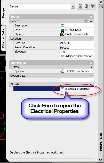
- To modify the electrical connectors of devices, Select the devices. On the Properties palette, expand Advanced, expand Circuits, and click Electrical Properties.
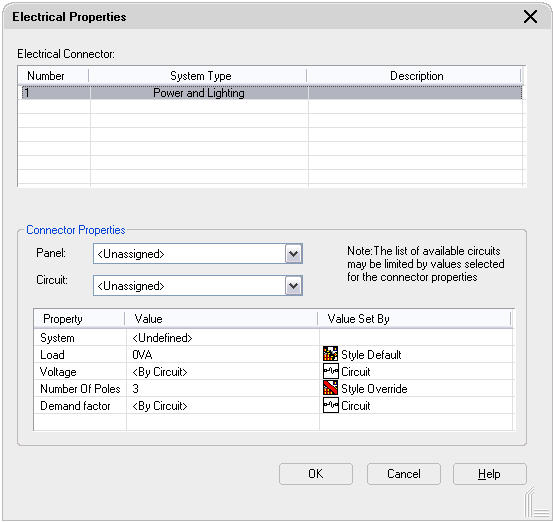
- On the Electrical Properties worksheet, select a connector. Select a circuit to assign the selected connector on all of the devices to it.
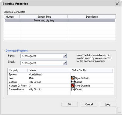
- Select Unassigned to remove any circuit assignments from the devices.
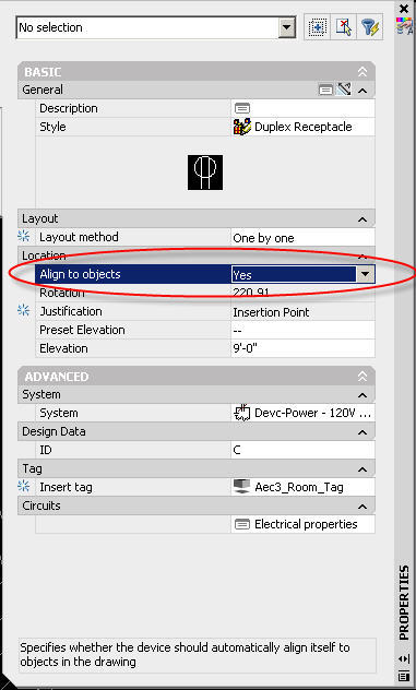
Device objects can auto-align to lines, arcs, circles, splines, polylines, walls, ceiling grids, and space boundaries.
Open the Power-Lighting Device tool palette, and select a receptacle tool.
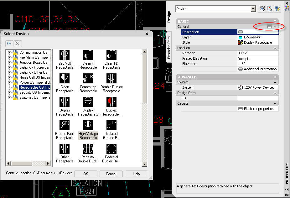
- On the Properties palette, change the style of the receptacle to be added by expanding Basic, and on the General bar, click properties. In the left pane of the Select Device worksheet, navigate to the drawing that contains the style. In the right pane, select the style, and click OK.
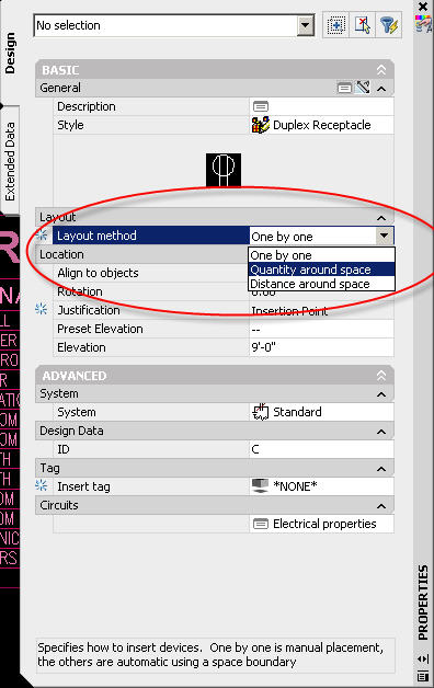
- In the Properties palette, expand Layout, and for Layou t method, select either "One by One"
- Expand Location, and for Align to objects, select Yes. This causes the receptacle to align to the object to which you snap. You can snap and align to a wall, ceiling grid, space boundary, line, polyline, spline, arc, or circle in the current drawing or in a referenced drawing (xref).
Device objects can be inserted along a Space Boundary either by Distance around Space or Quantity around Space
- On the Power-Lighting Device tool palette, select a receptacle tool.
- On the Properties palette, change the style of the receptacle to be added by expa nding Basic, and on the General bar , click properties. In the left pane of the Select Device worksheet, navigate to the drawing that contains the style. In the right pane, select the style, and click OK.
- Expand Layout, and for Layout method, select "Distance around space". For Distance between, enter a value. You can also enter a value by clicking and specifying 2 points in the drawing. In the drawing, move the cursor to the location for the first device. This must be a point on the space boundary.
- Examine the preview of the receptacle layout, and if necessary, move the cursor to a different location on the boundary.
- On the Properties palette, you can view the value for Number of devices. This read-only property is updated when the preview is displayed.
- Click to insert the receptacles, an d press Enter to end the command.
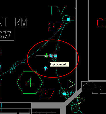
Grips on Wire objects have been improved to allow easier access to Wire mid-point grip and Tick Mark Location. In addition, a grip has been added to Flip the tick mark.
- Select the wires.
- On the Properties palette, expand Basic, and modify the basic properties as needed:
Spline Wire Segment:
Spline segment type has been added for Wires.
Manage Circuit Data through External References:
Electrical Project Database functionality has been expanded to allow Circuit Manager to detect loads on the entire project. Electrical Project Database notification is added to the Status bar and functions similar to the xref notification.
- You can use an electrical project database drawing to manage circuits across all drawings in a project.
- You can create circuits when you add a panel, or you can add circuits to panels later.
- You can configure circuit settings only in the drawing that contains the circuits. After you assign at least one device to a circuit, you cannot edit many of the circuit settings.
- You can assign devices to circuits as you add the devices, or you can add the devices first and then assign them to circuits later.
- You can keep circuit data current in multiple electrical drawings by reloading the project database.
- You can configure electrical preferences so that you are automatically notified of circuit overloads for power and lighting circuits.
- You can use circuit-checking features to see circuit information for a selected device. You can also check circuit connectivity to display which devices are assigned to the same circuit.
- As you refine your designs, you can move circuits around on a panel to balance loads. You can also drag and drop circuits from one panel to another.
- You can generate panel schedules automatically from the circuit data.
Electrical – Device Style and Panel Style Reorganization:
Device and Panel styles are reorganized and categorized to better suit the electrical design workflow.
Schematic – Electrical Schematic Symbol Style Reorganization:
Electrical based Schematic Symbol styles are reorganized and categorized to better suit the electrical design workflow.
Wire Size Calculator on Property Palette:
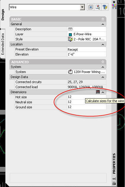
Electrical wire calculations are done by selecting the wire, and going to the properties palette, and click on
"calculate wire size" button.


No comments:
Post a Comment